Our Air Expert Insights Team brings decades of compressed air industry experience and unmatched technical expertise to deliver blogs, resources, and advice you can trust. Having served in roles like field technicians, engineers, sales, and customer support specialists, we’ve worked hands-on with the equipment we write about and know the premier brands we represent inside and out.
We’re dedicated to educating you before and after your purchase, helping you make informed decisions and maximize the value of your investment. Buying online should be seamless, but we believe convenience shouldn’t come at the expense of expert service.
Whether you’re researching a product, troubleshooting, or exploring your options, we’re here to guide you every step of the way.
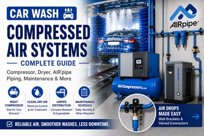
A dependable car wash compressed air system starts with the right compressor, but it does not stop there. Commercial car washes also need moisture control, reliable air treatment, properly sized distribution piping and dependable point-of-use connections.
This guide walks through the complete system — from rotary screw and piston air compressors to refrigerated dryers, AIRpipe aluminum piping, condensate management, equipment drops and preventive maintenance.
Most commercial car washes need an air compressor sized for the combined airflow demand of their pneumatic equipment, moisture separation and condensate management, an air dryer where required, filtration, corrosion-resistant compressed air distribution piping and properly sized point-of-use connections. Higher-volume automatic and tunnel washes often benefit from rotary screw compressors, while smaller or intermittent-demand operations may be well served by reciprocating piston compressors.
The Complete System
From the Compressor Room to the Wash Equipment
A car wash compressed air system should be designed as one connected air path. Moisture problems, restrictive components or undersized piping anywhere in that path can affect pneumatic equipment downstream.
Air Compressor
→
Air Receiver
→
Separator / Drain
→
Refrigerated Dryer
→
Filtration
→
AIRpipe Distribution
→
Car Wash Equipment
Car Wash Air Demand
Where Is Compressed Air Used in a Car Wash?
Pneumatic demand varies by wash design and equipment, but compressed air commonly supports equipment that cycles repeatedly throughout the operating day.
Chemical & Foamer Systems
Compressed air can support chemical and foam delivery equipment requiring reliable pneumatic operation.
Valves & Actuators
Pneumatic valves, cylinders and actuators may control repeated equipment movements throughout the wash.
Doors & Wash Equipment
Air-operated equipment may rely on stable pressure for frequent cycling throughout the day.
Maintenance Areas
Blow guns, pneumatic tools and maintenance stations may also connect to the facility compressed-air system.
Compressor Selection
What Type of Air Compressor Is Best for a Car Wash?
The best compressor depends on required CFM, operating pressure, simultaneous equipment use, operating hours and duty cycle.
High-Volume / Longer Duty Cycle
Oil-Injected Rotary Screw Compressors
Rotary screw compressors are a strong fit for busy tunnel, automatic and higher-volume car washes where compressed-air demand occurs throughout long operating periods.
They are well suited to applications that require a steady supply of compressed air over longer duty cycles.
A piston compressor may be appropriate for smaller car washes, maintenance areas or applications where compressed air demand is intermittent rather than continuous.
Proper sizing and duty-cycle limits still matter. Select the compressor around actual equipment requirements.
Compressing atmospheric air also concentrates the moisture already present in that air. As compressed air cools, water can condense inside receivers, dryers, filters and piping.
In a car wash environment, downstream moisture can affect pneumatic components and can become especially problematic during cold weather.
A refrigerated dryer is often a practical solution when a car wash needs to reduce moisture in compressed air before it reaches valves, actuators and other pneumatic equipment.
Dryer sizing should account for compressor airflow, inlet temperature, operating pressure and ambient conditions. A dryer that is too small may not adequately control downstream moisture during peak demand.
Separating moisture from compressed air is only part of the job. Condensate also has to be removed from receivers, separators, filters and other collection points.
Check Automatic Drains
A blocked or failed drain can allow collected water to remain inside the compressed-air system and potentially move downstream.
Atlas Copco WD 80
The WD 80 is an example of a condensate-management component that can be used as part of the compressed-air moisture control system.
What Type of Compressed Air Piping Is Best for a Car Wash?
The distribution network should deliver treated air without adding unnecessary restriction or contamination. Aluminum compressed-air piping provides a corrosion-resistant and modular alternative to traditional threaded ferrous piping.
Corrosion Resistant
Aluminum piping avoids internal rust and scale associated with traditional iron compressed-air piping.
Expandable
AIRpipe branches and outlet drops can be added as equipment, bays or facility layouts change.
Clean Distribution Path
Properly sized smooth-bore piping helps move treated compressed air throughout the facility.
Bring compressed air close to the equipment before transitioning to the point-of-use hardware. A consistent drop design can simplify maintenance and future equipment changes.
How Should Compressed Air Be Distributed to Multiple Wash Bays?
Multi-bay facilities should plan the main distribution system before individual drops are finalized. Locate the compressor room, dryer and filtration first, then route the AIRpipe main line so each wash area can receive an appropriately sized branch.
Standardize the Layout
Repeating common pipe sizes, valves and connection standards can simplify maintenance across several bays.
Plan Peak Demand
Size the system around realistic simultaneous equipment use, not simply the total number of available outlets.
Design for Expansion
Leave practical connection points for future bays, equipment or facility expansion.
Preventive Maintenance
How Often Should a Car Wash Compressed Air System Be Checked?
Car wash compressed-air systems should not be treated as “quarterly-only” equipment. Operators should perform routine daily checks, more detailed monthly inspections and any quarterly or scheduled service required by the specific compressor, dryer, filters and other components. Some compressors may require quarterly oil, filter or other service depending on the model, lubricant, operating hours and operating environment.
Daily Checks
Quick operating checks that can help identify a developing problem before it becomes a failure.
Oil / Fluid LevelCheck fluid level where applicable and investigate unexpected changes.
Operating PressureConfirm the compressor and system are maintaining expected pressure.
Operating TemperatureWatch for abnormal temperature changes or overheating.
Noise & VibrationListen for new sounds, excessive vibration or changes in normal operation.
LeaksCheck for visible or audible air, oil or condensate leaks.
Condensate DrainsConfirm automatic drains and collection points are actually discharging condensate.
Dryer StatusConfirm the refrigerated dryer is operating normally and not showing an alarm or fault.
Monthly Checks
Inspect components that can gradually become restricted, loose, dirty or worn.
Inlet FilterInspect for dirt, restriction and premature loading.
CoolersCheck cooling surfaces and airflow paths for dirt or obstruction.
Belts & CouplingsInspect condition, alignment and tension where applicable.
Dryer Condenser / VentilationKeep condenser surfaces and ventilation paths clean.
Filter ConditionInspect compressed-air filters and monitor pressure differential where available.
AIRpipe ConnectionsCheck pipe, fittings, wall brackets and valves for leaks.
Point-of-Use PressureCheck pressure at distant or high-demand pneumatic equipment.
Quarterly / Scheduled Service
These tasks are not universal quarterly requirements. Perform them when required by the OEM schedule, operating hours or actual component condition.
Compressor Oil ChangeSome compressors or operating conditions may require quarterly oil changes; others use different hour-based or calendar intervals.
Oil Filter ReplacementReplace according to the compressor manufacturer's service interval.
Separator ServiceInspect or replace the separator on oil-injected compressors according to OEM requirements.
Valve / Control InspectionInspect inlet, unload and control components when specified by the equipment manufacturer.
Dryer ServicePerform dryer-specific maintenance based on the model, operating conditions and service schedule.
Filter ReplacementReplace compressed-air filter elements based on pressure differential, hours or OEM interval.
Full Leak ReviewInspect the distribution system and correct leaks before they become an ongoing energy and performance issue.
Important: Maintenance intervals vary by compressor model, lubricant, operating hours, dryer type, filtration equipment and operating environment. Use the daily and monthly checks above as a preventive inspection framework, but always follow the manufacturer's service schedule for actual oil changes, filter replacement, separator service and other scheduled maintenance.
?
Need Help Planning Your Car Wash Air System?
Chat With an Air Expert
Not sure what size compressor, refrigerated dryer or AIRpipe system your car wash needs? Our Air Experts can help you work through airflow requirements, operating pressure, moisture control, piping layout and point-of-use connections.
If possible, have your number of wash bays, required PSI, estimated CFM and major pneumatic equipment available.
Get help planning the complete compressed-air system.
Can AIRpipe Be Added to an Existing Car Wash?
An existing car wash does not necessarily need to replace its entire compressed-air system to begin using aluminum AIRpipe. Appropriate transition fittings can allow AIRpipe to connect with existing compressed-air distribution systems.
Before converting or expanding the piping, confirm existing pipe diameter, thread type, working pressure, airflow capacity and equipment requirements.
Planning a new car wash, replacing an aging compressor or expanding an existing compressed-air system? Build the system around the complete airflow path instead of purchasing each component in isolation.
The correct compressor size depends on the combined CFM demand of the pneumatic equipment, required operating pressure, simultaneous equipment use and duty cycle. The number of wash bays alone is not enough to size the compressor correctly.
Rotary screw compressors are often a strong fit for higher-volume car washes with longer compressed-air duty cycles. Piston compressors may work well for smaller operations or intermittent air demand. Size the compressor around actual CFM, PSI and duty-cycle requirements.
Many car wash compressed-air systems benefit from a refrigerated dryer because moisture can affect pneumatic equipment and create cold-weather reliability problems. Dryer selection should account for airflow, pressure, inlet temperature and ambient conditions.
Atmospheric air naturally contains moisture. Compressing the air concentrates that moisture, and some of it condenses as the compressed air cools. Separators, drains, dryers and filters help remove that moisture before it reaches downstream equipment.
Aluminum compressed-air piping is a strong option because it is corrosion resistant and modular. The correct pipe diameter still depends on airflow demand, run length, pressure and acceptable pressure drop.
Car wash compressed-air systems should receive routine daily checks, more detailed monthly inspections and any quarterly or scheduled service required by the equipment manufacturer. Some compressors may require quarterly oil, filter or other service depending on model, lubricant, operating hours and operating environment.
No. Oil-change intervals vary by compressor model, lubricant, operating hours and operating conditions. Some equipment may require quarterly oil changes while other compressors use longer hour-based or calendar intervals. Follow the manufacturer's maintenance schedule.
Proper condensate separation, automatic drains, dryer performance, filtration and system design help reduce the amount of water available to freeze inside downstream piping and pneumatic equipment.
In many systems, AIRpipe can be transitioned to existing compressed-air piping using appropriate connectors. Confirm pipe diameter, thread type, working pressure, airflow requirements and component compatibility before making the transition.
Air Compressor Hose Size Guide: Choosing the Right Diameter & Length
Compare 1/4-inch, 3/8-inch and 1/2-inch compressed air hose and learn how tool CFM, operating pressure, hose length and fittings affect airflow at the point of use.
The right air hose should deliver enough airflow to the tool without creating unnecessary restriction between the compressed air piping system and the point of use. Hose inside diameter, hose length, operating pressure, couplers and the airflow requirement of the tool all affect performance.
In general, smaller hoses are easier to handle and work well for lower-demand or short-run applications. Larger-diameter hoses provide more airflow and are better suited to higher-CFM tools, longer hose runs and industrial workstations.
Quick Comparison
1/4" vs. 3/8" vs. 1/2" Air Hose
There is no single hose size that is correct for every air tool. Start with the tool manufacturer's airflow and pressure requirements, then account for hose length and the rest of the flow path.
1/4"Compact & Lower Demand
Best considered for short runs, portable tools and applications where flexibility and low hose weight matter more than maximum airflow.
3/8"Common Shop Size
A versatile choice for many garage, automotive and shop air tools where greater airflow is needed without moving to a large industrial hose.
1/2"Higher Airflow
Better suited to higher-demand tools, longer runs and industrial applications where minimizing restriction is more important than hose weight.
Important: These are general application categories, not universal CFM limits. Hose construction, length, fittings, pressure and manufacturer ratings all affect actual flow capacity. Always verify the hose and tool specifications before purchasing.
Inside Diameter Matters
How Air Hose Diameter Affects Airflow
Hose diameter determines how much space compressed air has to move through. As airflow demand increases, an undersized hose can become a restriction and contribute to pressure loss before the air reaches the tool.
1/4"
1/4-Inch Air Hose
Smaller and easier to handle, 1/4-inch hose is generally best reserved for lower-demand applications and shorter hose runs.
Compact pneumatic tools
Portable applications
Short hose runs
Applications prioritizing flexibility
3/8"
3/8-Inch Air Hose
3/8-inch hose provides a useful balance between airflow, flexibility and weight for many garage, automotive and general shop applications.
Impact tools
Automotive service
Garage drop stations
General pneumatic tools
Retractable hose reels
1/2"
1/2-Inch Air Hose
Larger hose can support higher airflow with less restriction and is worth considering for demanding tools, long runs or industrial workstation applications.
Higher-CFM equipment
Industrial workstations
Longer hose runs
High-flow air tools
Production environments
Selection Factors
Air Hose Size Comparison
Use this comparison as a starting point, then verify the requirements of the actual tool, hose, fittings and reel.
Hose Size
Relative Airflow
Flexibility
Typical Use
Watch For
1/4"
Lower
High
Light-duty tools, portable work and shorter runs
Can become restrictive with higher-demand tools
3/8"
Medium
Medium to High
Garage, automotive and general shop tools
Confirm flow capacity for demanding equipment
1/2"
Higher
Lower than smaller hose
Industrial, high-demand and longer-run applications
Greater weight and larger fittings/reels
Don't Oversize the Reach
How Air Hose Length Affects Pressure Drop
Hose length matters because compressed air experiences resistance as it travels through the hose. A longer hose creates more opportunity for pressure loss, especially when the hose diameter is small relative to the airflow demand.
Use the Shortest Practical Hose
Choose enough hose to comfortably reach the full work area, but avoid adding unnecessary length simply because a longer hose is available.
For a fixed workstation or drop station, position the hose reel so the required work area can be reached without routing excessive hose across the floor.
Drop Station Tip: Good reel placement can reduce the hose length required. Instead of compensating for poor drop placement with a very long hose, locate the AIRpipe drop and reel closer to the center of the intended work zone.
Ready to Shop?
Shop Compressed Air Hoses & Piping
Browse available compressed air hoses and AIRpipe system components. Use the sizing guidance on this page to narrow your requirements, then verify product diameter, length, pressure rating and connection type before ordering.
Diameter is only one part of hose selection. Material affects flexibility, weight, abrasion resistance, temperature behavior and how the hose feels during daily use.
Rubber Air Hose
Rubber hose is commonly selected for shop and industrial applications where flexibility, durability and abrasion resistance are important. Compare the specific hose's temperature and pressure ratings for the intended environment.
Polyurethane Air Hose
Polyurethane hose is typically lighter and can be useful where low weight and easy handling are priorities. Always compare the specific product's flexibility, abrasion resistance and pressure rating.
Hybrid / Other Hose Materials
Other constructions may combine characteristics intended to balance flexibility, durability, weight or environmental performance. Select based on the actual product specification rather than material name alone.
Don't Forget the Couplers and Fittings
A properly sized hose can still be restricted by undersized or incompatible fittings. The plug and coupler profile also needs to match the rest of the workstation so tools can be connected safely and consistently.
Not every hose in a compressed air system serves the same purpose. The 1/4-inch, 3/8-inch and 1/2-inch hose discussed in this guide refers primarily to flexible hose used between a workstation, hose reel and pneumatic tool.
Workstation / Tool Hose
Flexible air hose carries compressed air from a drop station or hose reel to the air tool. Selection focuses on tool CFM, working pressure, reach, flexibility and fitting compatibility.
AIRpipe System Flex Hose
AIRpipe systems may also use larger flexible connectors for connections between compressors, dryers, piping and other system equipment. These components serve a different purpose and should be selected according to the AIRpipe system design and connection size.
Building a Complete Workstation?
Size the Hose as Part of the Entire Drop Station
Hose diameter is only one part of point-of-use design. Drop size, regulators, manifolds, hose reels, couplers and fittings should all support the airflow required by the connected equipment.
Neither size is universally better. A 1/4-inch hose is lighter and easier to handle, while a 3/8-inch hose generally provides a less restrictive flow path for tools requiring more air. Choose based on tool demand, hose length and the specifications of the hose.
3/8-inch hose is commonly considered for many automotive and shop pneumatic tools, but the correct size depends on the impact wrench's required CFM and PSI, hose length, couplers and the capacity of the upstream air system. Check the tool manufacturer's specifications.
Longer hose increases resistance in the flow path and can contribute to pressure loss, particularly when airflow demand is high or hose diameter is small. Use only the length needed to comfortably cover the work area.
A larger hose cannot create compressor capacity that does not exist, but it may reduce restriction when an undersized hose is limiting airflow. Compressor output, piping, regulators, fittings and couplers also affect available pressure and flow.
No. Larger hose can provide greater flow capacity, but it is also heavier and may require larger reels and fittings. Select a hose that meets the tool's airflow requirement without adding unnecessary size and weight.
The hose must be rated for the pressure and operating conditions of the compressed air system. Never assume hose diameter determines its pressure rating. Verify the manufacturer's maximum working pressure for the specific hose before use.
Start with the airflow and pressure required by the tool, then choose the shortest practical hose length and a diameter that can support the application without unnecessary restriction. Complete the workstation with the right reel, couplers, fittings and AIRpipe drop components.
Air Hose Reel Selection Guide: How to Choose the Right Reel
Choose an air hose reel based on hose diameter, hose length, mounting position, rewind style, pressure rating and how the workstation will be used. Learn what to consider for garages, automotive service bays, workshops and industrial drop stations.
An air hose reel should do more than keep hose off the floor. The reel needs to provide enough hose to reach the entire work area while supporting the diameter, pressure and airflow required by the connected tools.
Reel placement is also part of compressed air system design. A properly located reel can shorten the hose run, reduce clutter around the workstation and make an AIRpipe drop station easier to use throughout the day.
Quick Selection Guide
Which Type of Air Hose Reel Is Right for You?
Retractable / Spring Rewind
A strong choice for garages, service bays and workstations where the hose is used frequently and needs to retract quickly after use.
Manual Rewind
Useful where simple construction, controlled rewinding or longer hose capacity is more important than automatic retraction.
Heavy-Duty Industrial Reel
Designed for frequent use, demanding environments or larger hose where durability, mounting strength and serviceability are priorities.
Don't choose a reel based on hose length alone. Confirm hose inside diameter, maximum working pressure, inlet and outlet connection size, mounting requirements and the airflow demand of the tools being supplied.
Compare Reel Styles
Retractable vs. Manual Air Hose Reels
Rewind style changes how the reel is used, where it can be installed and how quickly the hose can be stored after each job.
Popular for Workstations
Retractable / Spring-Rewind Hose Reel
A spring mechanism retracts the hose into the reel after use. This style works well where operators repeatedly pull out and return the hose throughout the day.
Fast hose storage
Helps keep floors clear
Useful for wall or ceiling mounting
Well suited to fixed drop stations
Good for frequent-use work areas
Simple & Controlled
Manual-Rewind Hose Reel
The operator rewinds the hose using a handle or crank. Manual reels can be useful when automatic rewind is not required or when longer or heavier hose is being managed.
Simple operating design
Controlled rewinding
Useful for longer hose runs
No spring-rewind mechanism
Available for fixed or mobile applications
High-Duty Use
Industrial-Duty Hose Reel
Industrial reels are designed around demanding environments, frequent use and heavier construction. Depending on the model, they may use spring, manual or powered rewind systems.
Manufacturing workstations
Automotive service facilities
Fabrication environments
Frequent daily hose cycles
Higher-capacity hose configurations
At a Glance
Air Hose Reel Type Comparison
Reel Type
Rewind Method
Good Fit For
Advantages
Consider
Retractable / Spring
Automatic spring rewind
Garage, service bay, workshop and fixed workstation
Fast storage and cleaner work area
Hose size, spring mechanism and mounting location
Manual Rewind
Hand crank
Longer hoses, controlled storage and general shop use
Simple operation and controlled rewind
Requires manual hose storage
Industrial Duty
Varies by reel
Manufacturing, fabrication and demanding service
Durable construction and frequent-use capability
Mounting, hose capacity and application requirements
Size the Flow Path
How to Choose Air Hose Reel Size
The reel must support both the physical hose and the compressed air requirements of the workstation. Work through these factors before selecting a reel.
1
Choose the Hose Diameter First
Hose diameter should be based on the airflow required by the connected tools. The reel then needs to accommodate that diameter without becoming the restriction in the system.
Determine the farthest point the hose needs to reach from the planned reel location. Include normal tool movement, vehicle access or workstation coverage.
Measure from the reel location to the work area.
Allow practical working slack.
Avoid adding excessive hose "just in case."
Consider whether moving the reel would reduce required length.
3
Confirm the Reel's Pressure Rating
The reel, hose and connections must be suitable for the operating pressure of the compressed air system. Do not assume all reels support the same maximum working pressure.
4
Check Inlet and Outlet Connection Sizes
A large hose attached through restrictive reel connections can still limit flow. Compare the reel's inlet, outlet and swivel connection sizes with the rest of the drop station.
5
Match the Reel to the Duty Cycle
Consider how frequently the reel will be used and the environment where it will operate. An occasional-use garage reel and a reel cycling throughout an industrial shift may have very different construction requirements.
Put the Reel Where the Work Happens
Wall vs. Ceiling vs. Workstation Mounting
Hose reel location determines the work radius, how much hose is required and whether the hose crosses work or traffic areas.
Wall Mount
A practical choice beside workbenches, machines or service bays. Wall mounting keeps the reel accessible and can provide a natural connection point beneath an AIRpipe drop.
Ceiling / Overhead Mount
Overhead mounting can help keep hose above walkways and work surfaces while providing coverage around a service bay or central work area.
Bench / Workstation Mount
Mounting directly at a workstation can provide convenient tool access where the work remains concentrated in one area.
Drop Station Tip: Treat reel placement and AIRpipe drop placement as one decision. Moving the drop closer to the center of the work zone can reduce hose length and improve workstation organization.
Part of the Complete Workstation
Connect the Reel to an AIRpipe Drop Station
The hose reel is only one component in the point-of-use airflow path. Drop size, shutoff valves, filters, regulators, manifolds, fittings and hose diameter all need to support the equipment connected downstream.
Browse compressed air piping, hoses and related components for your workstation. Verify hose diameter, reel capacity, pressure rating and connection size against your application before ordering.
A retractable reel can keep hose organized while providing reach for tire inflation, impact tools, detailing and other garage projects.
Prioritize convenient mounting
Match hose size to tool demand
Cover the vehicle/work area
Automotive
Service Bay Hose Reel
Automotive work benefits from reel placement that lets the hose reach around a vehicle without creating unnecessary hose across adjacent bays or walkways.
Frequent-use construction
Appropriate impact-tool airflow
Wall or overhead mounting
Industrial
Industrial Hose Reel
Manufacturing and fabrication environments may require more durable reel construction, larger hose and higher-frequency operation.
Match duty cycle to application
Confirm flow and pressure ratings
Provide service access
Common Questions
Air Hose Reel FAQs
Choose the hose diameter based on the airflow requirements of your tools first, then select a reel capable of holding the required hose diameter and length. Also confirm the reel's pressure rating, inlet size and intended duty level.
Neither type is universally better. Retractable reels provide convenient automatic hose storage and work well for frequent-use workstations. Manual reels provide controlled hand-crank rewinding and may be appropriate for longer or heavier hose configurations.
Wall mounting works well beside fixed workstations and service areas. Ceiling or overhead mounting can help keep hose above floors and walkways while providing coverage around a larger work area. Choose the position that provides the required reach with the least unnecessary hose length.
Any component in the compressed air flow path can create resistance. Reel connections, swivels, hose diameter, hose length and fittings should be sized so they do not unnecessarily restrict the airflow required by the tool.
A 3/8-inch hose is commonly used with many automotive pneumatic tools, but suitability depends on the specific impact wrench's airflow requirement, hose length, fittings, reel flow capacity and upstream compressed air system. Verify the tool and reel specifications.
Position the reel where it can cover the intended work zone while keeping the hose path organized and the reel accessible for service. The AIRpipe drop, regulator, manifold and reel should be planned together rather than selecting reel location after the piping layout is complete.
Choose a hose reel that supports the required hose diameter, provides enough reach for the work area and matches the pressure and duty requirements of the application. Then connect it to a properly designed AIRpipe drop with the correct regulator, manifold, fittings and couplers.
Air Fitting Types Explained: Industrial, Automotive, ARO & V-Style
Learn how common compressed air fitting profiles differ, how plugs and couplers work together, and what to consider when selecting Industrial, Automotive, ARO and V-Style fittings for hoses, tools and AIRpipe drop stations.
Compressed air fittings connect hoses, tools, reels, manifolds and other point-of-use equipment. While many fittings may look similar, plugs and couplers can use different profiles that are not automatically interchangeable.
The connection profile is only part of the decision. Port size, thread type, airflow capacity, pressure rating and the demands of the air tool also matter. A fitting that physically connects can still become a restriction if it is too small for the application.
Quick Comparison
Common Air Fitting Profiles
These are several common profiles found on compressed air hoses, tools and shop equipment. Always confirm the specific plug and coupler specifications before assuming two fittings will connect.
Industrial / M-Style
A widely used general-purpose fitting profile commonly found in garages, workshops and pneumatic tool applications.
Automotive / T-Style
Common in automotive and shop environments. The plug profile differs from standard Industrial-style fittings.
ARO / A-Style
Another established compressed air connection profile used with compatible ARO-style plugs and couplers.
V-Style / High Flow
Designed around a larger internal flow path where reducing restriction is important for higher-air-demand applications.
Do not assume similar-looking fittings are interchangeable. Plug shape, locking geometry and coupler design can differ between fitting families. Confirm compatibility before connecting components.
Know the Profile
Industrial, Automotive, ARO and V-Style Air Fittings
Each fitting family uses a particular plug and coupler geometry. Matching the correct profile helps create a secure connection and consistent compressed air setup across the shop.
Common General-Purpose Profile
Industrial / M-Style Air Fittings
Industrial-style fittings are widely used in general compressed air applications and are commonly seen on pneumatic tools, shop hoses and hose reels.
General shop use
Garage air systems
Pneumatic tools
Hose reels
Point-of-use drops
Automotive Profile
Automotive / T-Style Air Fittings
Automotive-style fittings are common in service and repair environments. Their plug profile differs from Industrial-style fittings, so compatibility should be verified before connecting.
Automotive repair
Service bays
Tire service
Impact tools
General shop air
Alternate Standard
ARO / A-Style Air Fittings
ARO-style fittings use their own plug geometry and should be paired with compatible couplers. They may be found in established compressed air systems where a specific fitting standard has already been adopted.
Existing shop systems
Pneumatic equipment
Tool connections
Dedicated fitting standards
High-Flow Option
V-Style / High-Flow Air Fittings
V-Style or other high-flow fitting designs are intended to provide a less restrictive internal air path for applications where higher airflow is important.
Higher-CFM pneumatic tools
Demanding automotive tools
Industrial workstations
Applications sensitive to pressure drop
At a Glance
Air Fitting Type Comparison
Fitting Type
Also Known As
Typical Environment
Main Consideration
Interchangeability
Industrial
M-Style
Garage, workshop, general pneumatic tools
Common general-purpose connection
Use matching Industrial-profile plug/coupler unless the coupler is specifically designed for multiple profiles
Automotive
T-Style
Automotive service and repair
Different plug geometry from Industrial style
Verify coupler profile before connecting
ARO
A-Style
Existing shop systems and pneumatic equipment
Requires compatible ARO-style connection
Do not assume compatibility with Industrial or Automotive
V-Style
High Flow
High-air-demand tools and industrial use
Larger flow path intended to reduce restriction
Confirm the coupler supports the V-style plug
Plug + Coupler + Thread
Understanding Air Plugs, Couplers and Adapters
A complete compressed air connection often involves more than one interface. The fitting profile determines how the plug fits the coupler, while the threaded connection attaches the fitting to the hose, tool, regulator, manifold or reel.
AIRpipe Drop / Manifold
→
Coupler
→
Plug + Tool / Hose
Plug Profile
The plug is the male quick-connect component. Its shape must be accepted by the coupler being used.
Coupler Profile
The coupler locks onto the plug and opens the compressed air path when connected. Some couplers are designed for one profile while others may support multiple profiles.
Thread Size
Thread size describes how the plug or coupler attaches to the hose, reel, manifold, regulator or tool. It is separate from the quick-connect profile.
Connecting Different Components
When Do You Need an Air Hose Adapter?
Air hose adapters can help connect components with different thread sizes or connection types. They are useful when adding tools, reels, manifolds or accessories to an existing compressed air workstation.
Thread-Size Adapter
Used when two components have different threaded port sizes. The adapter changes the mechanical connection but does not automatically change the plug/coupler profile.
Quick-Connect Adapter
Used to add a compatible quick-connect plug or coupler to a threaded hose, manifold, regulator, reel or tool.
Reducer / Enlarger
Changes connection size between components. Avoid unnecessary reductions when they could restrict airflow to a demanding pneumatic tool.
System Transition
Transition fittings can also be used where AIRpipe connects to an existing compressed air piping system or other equipment.
Every fitting adds another passage through which compressed air must flow. A restrictive fitting or coupler can limit performance even when the hose and upstream piping are properly sized.
Look at the Entire Air Path
Air flows through the main piping, drop, valve, regulator, manifold, fittings, reel and hose before reaching the tool. The smallest or most restrictive component can influence the performance of the entire workstation.
Higher-demand tools: If a pneumatic tool requires substantial airflow, evaluate the hose diameter, reel connections and coupler flow path together rather than simply increasing compressor pressure.
Fittings Are Only Part of the Flow Path
Match the Fitting to the Right Air Hose
A high-flow coupler cannot compensate for an undersized hose. Choose hose diameter and length based on tool demand, then select fittings that support that same airflow requirement.
Using a consistent fitting profile across hoses, reels, manifolds and tools can make a compressed air workstation easier to use and maintain. Plan the fitting standard when designing each AIRpipe drop station.
Browse piping, hoses, fittings and related compressed air components for your workstation. Verify connection profile, thread size, pressure rating and airflow requirements before ordering.
Common compressed air fitting profiles include Industrial or M-Style, Automotive or T-Style, ARO or A-Style and high-flow profiles such as V-Style. Other fitting profiles also exist, so verify the plug and coupler specifications used in your system.
Not automatically. Industrial and Automotive fittings use different plug profiles. A coupler specifically designed to accept multiple profiles may support both, but standard single-profile couplers should be matched to the correct plug.
The plug is the male quick-connect component and the coupler is the female component that locks onto the plug. The plug and coupler profiles must be compatible for the connection to work correctly.
Yes. Fittings, couplers and threaded ports can create resistance in the compressed air path. Undersized or restrictive connections can contribute to pressure loss, particularly when supplying higher-air-demand tools.
A high-flow fitting is designed with a larger or less restrictive internal air path than many standard quick-connect fittings. It may be useful for tools or workstations with greater airflow demand, provided the rest of the compressed air system can support that flow.
AIRpipe can often transition into existing steel, aluminum or other compressed air systems using the correct transition fittings and connectors. Confirm pipe dimensions, connection method, thread type, pressure rating and system compatibility before making the transition. Review the AIRpipe Compatibility & Transition Chart for additional guidance.
Choose Fittings That Support the Entire Workstation
Match the plug and coupler profile first, then verify thread size, pressure rating and airflow capacity. A consistent fitting standard across your hoses, reels, manifolds and tools can make an AIRpipe drop station easier to use, maintain and expand.
Compressed Air Manifold Guide: How to Choose the Right Manifold
Learn how to choose a compressed air manifold by inlet size, number of outlets, airflow, pressure rating and workstation demand. See where manifolds fit into AIRpipe drop stations for garages, service bays and industrial work areas.
A compressed air manifold takes one air supply and divides it into multiple outlet ports. In a drop station, that means one AIRpipe drop can supply multiple hoses, tools or point-of-use connections without requiring a separate branch for every outlet.
The manifold itself should not become a bottleneck. Inlet size, outlet size, the number of tools operating at the same time and the total airflow demand all matter when selecting a manifold.
Quick Selection Guide
When Should You Use an Air Manifold?
Multiple Tools at One Workstation
Use a manifold when several pneumatic tools or hoses need convenient access from the same compressed air drop.
One Drop Serving Multiple Bays
A manifold can provide separate outlets for nearby work positions when the airflow demand and layout support it.
Future Expansion
Extra manifold ports can make it easier to add another hose, reel or workstation accessory later without rebuilding the drop.
More ports do not create more compressed air. The AIRpipe drop, manifold inlet, upstream piping and compressor still need enough capacity to supply the combined demand of the equipment operating at the same time.
Where the Manifold Fits
Typical AIRpipe Drop Station With a Manifold
A manifold normally sits near the point of use, after the main AIRpipe drop and any required isolation or air-preparation components.
AIRpipe Main Line
→
Drop + Shutoff
→
Filter / Regulator
→
Air Manifold
From the manifold: individual outlets can feed couplers, hose reels, hoses or dedicated pneumatic equipment. The exact order of point-of-use components can vary by application.
Size for the Workstation
How to Choose a Compressed Air Manifold
Start with what the manifold needs to supply. The correct manifold depends less on the physical number of ports and more on the airflow and pressure required by everything connected downstream.
1
Determine How Many Outlets You Need
Count the hoses, reels, tools or pieces of equipment that need a connection at the workstation.
Include connections used at the same time.
Consider whether an extra outlet would help future expansion.
Do not add unnecessary ports simply because they are available.
2
Calculate the Realistic Simultaneous Air Demand
If several outlets may be used at once, the manifold and upstream drop need enough capacity to support the combined airflow requirement.
Example: A four-port manifold does not necessarily need to support four tools operating at once if the workstation only uses one tool at a time. Design for realistic simultaneous demand.
3
Check the Manifold Inlet Size
The inlet should support the total airflow entering the manifold. A restrictive inlet can limit every outlet downstream, even if the outlet ports themselves are adequately sized.
4
Match Outlet Size to the Hose and Equipment
Outlet connections should work with the hoses, reels, couplers and tools being supplied. Avoid unnecessary reducers where they could create additional restriction.
The manifold must be suitable for the operating pressure of the compressed air system. Verify the manufacturer's maximum working pressure for the specific manifold before installation.
6
Decide Whether Each Outlet Needs Its Own Control
Some manifolds simply divide the air supply, while others may be paired with individual valves, couplers or downstream regulators depending on the workstation.
Individual outlet shutoffs can help isolate equipment.
Different tools may require different regulated pressures.
Unused outlets should be properly capped or controlled.
At a Glance
Air Manifold Selection Factors
Factor
Why It Matters
What to Check
Common Mistake
Number of Ports
Determines how many downstream connections are available.
Current needs plus reasonable future expansion.
Assuming more ports means more airflow capacity.
Inlet Size
Controls the flow path feeding all manifold outlets.
Match to combined airflow demand and upstream connection.
Using a restrictive inlet with high-demand tools.
Outlet Size
Connects the manifold to hoses, reels or equipment.
Hose diameter, coupler size and equipment requirements.
Adding unnecessary reducers.
Pressure Rating
Determines whether the manifold is suitable for system pressure.
Manufacturer's maximum working pressure.
Selecting only by thread size.
Simultaneous Demand
Determines how much total air must pass through the manifold.
CFM required by tools that may operate at the same time.
Sizing each outlet separately without checking combined demand.
Build Around the Work
Where Should an Air Manifold Be Installed?
Install the manifold where its outlets are accessible and where hoses or reels can connect without creating unnecessary clutter or long flexible runs.
Workstation Manifold
Mounting the manifold near a bench, machine or service bay keeps several connections available in one organized location.
Hose Reel Manifold
A manifold can feed multiple hose reels from one AIRpipe drop when the upstream flow capacity supports the combined demand.
Equipment Manifold
Industrial work areas may use a manifold to feed several pneumatic devices or machines from one branch or drop.
Don't Create a Bottleneck Downstream
Match the Manifold to the Hose and Fittings
Manifold size, hose diameter, couplers and fittings should support the same airflow requirement. A properly sized manifold can still be restricted by small hoses or restrictive fittings.
If the manifold outlets use quick-connect couplers, choose a consistent fitting profile that matches the hoses and tools used throughout the workstation.
A small manifold can provide convenient connections for inflation, impact tools, blow guns and other garage equipment from one AIRpipe drop.
Easy-access couplers
Simple future expansion
One organized connection point
Automotive
Automotive Service Bay Manifold
A service-bay manifold can feed a hose reel, tire equipment or additional tool connections from a central drop.
Impact-tool airflow
Reel connections
Multiple service outlets
Organized bay layout
Industrial
Industrial Workstation Manifold
Manufacturing and fabrication areas may use manifolds to distribute air to multiple production tools or pieces of pneumatic equipment.
Higher combined airflow demand
Multiple machine connections
Isolation and service access
Part of the Complete Workstation
Plan the Manifold With the AIRpipe Drop
The manifold should be selected as part of the full drop station, including the AIRpipe branch, shutoff valve, regulator, hose reel, hose and fittings.
Browse compressed air piping, hoses, fittings and related workstation components. Verify inlet size, outlet size, pressure rating and airflow requirements before ordering.
A compressed air manifold divides one compressed air supply into multiple outlet connections. It can allow several hoses, tools or pieces of pneumatic equipment to connect to one drop or branch.
Choose enough ports for the hoses, tools or equipment that need connections, while allowing reasonable room for future expansion. The number of ports does not determine airflow capacity; inlet size and simultaneous air demand also matter.
A manifold can contribute to restriction if its inlet, internal passages or outlet connections are undersized for the airflow demand. Select the manifold based on the combined demand of the equipment that may operate at the same time.
Yes, provided the compressor, upstream piping, AIRpipe drop, manifold and downstream connections can supply the combined airflow and pressure required by the tools operating simultaneously.
If every outlet needs the same regulated pressure, a regulator can be placed upstream of the manifold when appropriately sized for the combined flow. If different outlets require different pressures, individual downstream regulators may be appropriate. Follow the requirements of the connected equipment.
Install the manifold near the point of use where its outlets are accessible and where hoses or reels can connect without unnecessary length or clutter. Plan the manifold location together with the AIRpipe drop, regulator, hose reels and workstation layout.
Choose the number of outlets you need, then make sure the inlet, manifold passages, couplers, hoses and AIRpipe drop can support the combined airflow required by the workstation. A properly planned manifold can make the compressed air system easier to use today while leaving room to add another connection later.
Industrial Compressed Air Drop Stations: Workstation Design Guide
Design industrial compressed air drops for manufacturing, fabrication, assembly and production workstations using AIRpipe, properly sized branches, isolation valves, regulators, manifolds, hose reels and compatible fittings.
Industrial compressed air workstations often have higher or more continuous airflow demand than garage or general service applications. A production station may supply several pneumatic tools, cylinders, assembly equipment or process devices throughout a shift.
That makes workstation design an extension of the entire compressed air distribution system. The AIRpipe branch, drop, valves, regulator, manifold, fittings and flexible hose should all support the pressure and airflow required at the point of use.
Core Industrial Drop Components
What Goes Into an Industrial Drop Station?
AIRpipe Branch & Drop
Carries sufficient airflow from the plant distribution system to the production workstation.
Isolation Valve
Allows the workstation or equipment connection to be serviced without unnecessarily affecting other areas.
Air Preparation
Filters, regulators or other point-of-use treatment may be required based on the equipment and process.
Distribution at the Station
Manifolds, fittings, reels and hoses deliver air from the drop to individual tools or machines.
From Plant Air to Production
Typical Industrial AIRpipe Drop Station
The exact arrangement depends on the process, but an industrial point-of-use connection commonly follows this general path.
AIRpipe Main Line
→
Branch / Drop
→
Isolation + Air Prep
→
Manifold / Equipment
Industrial design principle: size the drop for the realistic simultaneous demand of the workstation—not simply the nominal size of the tool connection.
Work From Demand Backward
How to Design an Industrial Compressed Air Drop
Start with what the equipment needs at the workstation and work backward toward the AIRpipe distribution line.
1
Identify Every Air Consumer at the Workstation
List pneumatic tools, machines, actuators and process equipment that may draw air from the drop.
Assembly tools
Impact or fastening tools
Pneumatic cylinders
Blow-off stations
Fabrication tools
Process equipment
2
Determine Simultaneous CFM Demand
Determine which devices may operate at the same time and calculate the realistic combined airflow requirement.
Do not size the workstation from average plant demand alone. Short-duration peak demand at the drop can still cause pressure loss or poor tool performance.
3
Confirm Required Operating Pressure
Determine the pressure required by each connected device and whether the workstation should operate at one regulated pressure or several different downstream pressures.
4
Size the Branch and Drop
The AIRpipe branch should be capable of carrying the workstation demand without creating excessive pressure loss. Larger or higher-demand production areas may require more capacity than a typical tool drop.
A workstation isolation valve can simplify service and maintenance. Add filtration, regulation or other air treatment based on equipment and process requirements.
Decide whether the station will use a manifold, flexible hose, hose reel, direct equipment connection or a combination of these components.
Keep flexible hose as short as practical.
Match hose diameter to airflow demand.
Avoid restrictive fittings and unnecessary reducers.
Provide service access to connections.
Industrial Workstation Components
Build the Drop Around the Process
Distribution
AIRpipe Branch & Drop
Supplies the workstation from the main compressed air distribution system. Size the branch around actual airflow rather than choosing pipe diameter by connection size alone.
Isolation
Shutoff Valve
Provides a practical point to isolate the workstation, machine or production area for maintenance.
Pressure & Quality
Filter / Regulator
Controls downstream pressure and provides point-of-use filtration when required by the process or equipment.
Multiple Connections
Compressed Air Manifold
Divides one drop into multiple outlets for tools or equipment when the upstream system can support combined demand.
A large AIRpipe main line cannot compensate for a restrictive final workstation. The branch, valves, regulator, manifold, fittings and flexible hose all affect the air that reaches the equipment.
Evaluate the Entire Flow Path
When production equipment experiences pressure loss, check the complete path rather than immediately increasing compressor discharge pressure.
The restriction may be at the regulator, quick coupler, hose, manifold inlet or another point-of-use component.
Industrial Use Cases
Compressed Air Drop Stations by Application
Manufacturing
Assembly Workstation
Assembly stations may need several pneumatic fastening tools, blow-off connections or actuators operating throughout a shift.
Consistent regulated pressure
Multiple tool connections
Accessible isolation
Reliable airflow during peak demand
Fabrication
Fabrication Workstation
Grinders, sanders, impact tools and other pneumatic equipment can create higher intermittent airflow demand.
Higher-flow drop design
Appropriate hose diameter
High-flow fittings where needed
Durable hose or reel selection
Production Equipment
Machine Connection
Pneumatic machines may require a dedicated branch, shutoff and regulated supply rather than sharing a general-purpose tool drop.
Dedicated airflow capacity
Machine-specific pressure
Service isolation
Direct or flexible connection
Related Commercial Application
Designing Compressed Air for a Car Wash?
Car washes combine repeated pneumatic demand with moisture-control and distribution challenges. See how compressor selection, refrigerated drying, condensate management, AIRpipe distribution and point-of-use connections work together in automatic, tunnel and multi-bay wash facilities.
A manifold can efficiently serve several tools when they operate from the same workstation and the combined airflow demand is within the capacity of the drop.
Expanding an Existing Plant?
AIRpipe Can Often Transition Into Existing Compressed Air Systems
Adding a new production line or workstation does not always require replacing the existing compressed air network. AIRpipe can often be connected using the appropriate transition method after confirming pipe dimensions, material, operating pressure and compatibility.
Work through drop placement, airflow, hose sizing, reel position, manifolds, fittings and point-of-use air preparation before finalizing the workstation.
Browse AIRpipe distribution components, compressed air hoses and related accessories for industrial workstations. Verify airflow, connection size, pressure rating and application requirements before ordering.
Start with the realistic simultaneous airflow and pressure requirements of the tools or equipment supplied by the workstation. Then size the AIRpipe branch, valves, regulator, manifold, fittings and flexible connections so they can support that demand without creating an unnecessary restriction.
Not necessarily, but high-demand or important production equipment may benefit from a dedicated branch and isolation point. Multiple lower-demand devices can sometimes share one appropriately sized manifold or workstation drop.
Place regulation where it provides the required pressure control for the connected equipment while remaining accessible for adjustment and service. If multiple devices require different pressures, individual downstream regulators may be appropriate.
Yes, provided the AIRpipe branch, manifold and downstream components can supply the combined airflow required by the tools that may operate simultaneously.
Common causes include undersized branch piping, restrictive regulators, small couplers, long or undersized flexible hoses, manifold restrictions and simultaneous demand that exceeds the capacity of the drop.
AIRpipe can often transition into existing steel, aluminum or other compressed air systems using appropriate transition fittings. Verify pipe dimensions, pressure rating, connection method and compatibility before making modifications.
Deliver the Right Air to Every Industrial Workstation
Start with the airflow and pressure required by the process, then size the AIRpipe branch, drop, isolation, regulator, manifold, hose and fittings around that demand. A properly designed workstation can support current production while leaving a practical path for future equipment and expansion.
Plan a complete compressed air system from the AIRpipe distribution line to the point of use. Choose the number of outlet stations you need, then learn how to select drop locations, hose size, hose reels, fittings, manifolds, filters, regulators and lubricators for garages, service bays, workshops and industrial workstations.
Garage to PlantLayouts for DIY and industrial applications
Build From the Main Line Out
Everything You Need to Build a Compressed Air Drop Station
A compressed air system does not end when the main piping reaches the wall. The drop station is where clean, regulated compressed air becomes usable at each workstation. If you are starting from scratch, begin with an AIRpipe Garage Kit sized for the number of outlet stations you need. If the piping is already installed, use this resource center to finish each drop with the right hose, reel, couplers, manifold and point-of-use air treatment.
Starting With the Piping System?
Start With the Number of AIRpipe Stations You Need
Our preconfigured AIRpipe Compressed Air Garage Kits build the distribution side of the system from the compressor to one or more outlet stations. Choose the kit that matches your shop layout, then use the guides below to finish each workstation with the appropriate hose, reel, fittings, manifold and point-of-use air preparation.
Skip the piping-kit step and go directly to the drop station. Start with workstation demand, then choose the hose, reel, fittings, manifold and air preparation needed at the point of use.
Start Here
What Is a Compressed Air Drop Station?
A drop station is the point where compressed air leaves the main distribution piping and is prepared for use at a workstation, machine, service bay or tool connection.
Typical AIRpipe Drop Station Layout
The exact configuration depends on the application, but a complete workstation commonly follows this path:
AIRpipe Main Line
→
Vertical Drop
→
Shutoff Valve
→
FRL / Filter
→
Manifold
→
Hose Reel
→
Air Tool
The goal is simple: deliver adequate airflow and pressure where work happens while keeping hoses organized and allowing the station to be isolated, regulated and expanded when needed.
Featured September Guide
How to Design an AIRpipe Drop Station
Start with workstation location and airflow demand, then determine drop placement, mounting height, hose reach, point-of-use air treatment and connection type. Our complete design guide walks through the layout from the AIRpipe main line to the tool.
Most stations use some combination of these components. The right configuration depends on flow demand, tool requirements and how the workstation is used.
AIRpipe Drop
Carries compressed air from the main distribution line down to the workstation.
Shutoff Valve
Isolates the station for maintenance, equipment changes or future expansion.
Filter / Regulator / Lubricator
Conditions compressed air and controls outlet pressure based on the connected application.
Drop stations handle compressed air at the point of use, while dryers, filters and separators protect the larger compressed air system. Use our Air Treatment Resource Center to choose and size the equipment upstream of your AIRpipe distribution system.
Drop stations are one part of the complete compressed air distribution system. If you are still planning the piping network, use the Garage Kit hub or these AIRpipe resources for station count, main-line sizing, piping material, layout and system economics.
Build an AIRpipe System That Can Grow With Your Shop
Start with a preconfigured AIRpipe Garage Kit or design the distribution system around your facility, then complete each outlet with the hose reel, hose, manifold, filter, regulator and fittings required by the work performed there. A modular layout makes it easier to add another workstation as your garage, shop or facility expands.
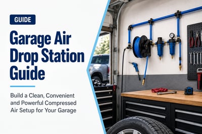
Garage Air Drop Station Guide: Build a Better Compressed Air Workstation
Build a clean, expandable compressed air system for your garage. Start with an AIRpipe piping layout sized for the number of workstations you need, then finish each drop with the right hose reel, air hose, regulator, fittings and optional manifold.
A garage air drop station brings compressed air from the main piping system to the area where you actually work. Instead of dragging one long hose from the compressor, AIRpipe can distribute compressed air around the garage and place convenient connections near workbenches, vehicle bays and tool areas.
There are really two parts to the system: first, the AIRpipe distribution network that creates one or more outlet stations; second, the workstation equipment attached to each outlet, such as the regulator, hose reel, hose, couplers and manifold.
Building the Piping System First?
Choose the Number of AIRpipe Stations Your Garage Needs
AirCompressors.com offers preconfigured AIRpipe Garage Kits for 1, 3, 4 or 5 outlet stations. These kits handle the distribution side of the project. Once the AIRpipe outlets are installed, use the rest of this guide to finish each workstation with hose, reel, fittings and point-of-use air preparation.
You do not need another piping kit. Skip directly to workstation design and choose the hose, reel, fittings, manifold and air preparation required at each existing drop.
Typical Garage Workstation
The Core Garage Drop Station Components
AIRpipe Drop
Brings compressed air from the main garage piping loop or branch down to the point of use.
Regulator / Filter
Controls workstation pressure and can provide additional point-of-use filtration where needed.
Hose Reel + Hose
Provides the working reach around the garage while helping keep hose organized and off the floor.
Fittings / Manifold
Connects tools and can provide multiple outlets when the workstation needs more than one air connection.
From Compressor to Air Tool
Typical Garage AIRpipe Drop Station Layout
The AIRpipe Garage Kit handles the distribution side of this path. The drop station finishes the connection from the AIRpipe outlet to the tool.
Work backward from the tools and work area. The best drop position is usually the one that minimizes flexible hose while keeping the workstation convenient to use.
1
Identify Your Main Work Area
Decide where compressed air will be used most often. That might be beside a workbench, near the center of a vehicle bay or along a wall where pneumatic tools are stored.
Vehicle maintenance area
Workbench
Tire inflation area
Detailing area
Woodworking or fabrication area
2
List the Air Tools You Use
Determine the PSI and airflow requirements of the tools that will use the station. Common garage tools can include impact wrenches, ratchets, blow guns, inflators, nailers, die grinders and other pneumatic equipment.
Design around the highest realistic airflow demand rather than assuming every garage tool uses the same amount of air.
3
Position the Drop Near the Work Zone
Place the AIRpipe drop where the reel or hose can reach the full work area without requiring excessive hose length.
Avoid routing hose across major walkways.
Keep regulators and valves accessible.
Consider where another garage drop could be added later.
4
Choose Hose Diameter and Length
Hose size should support the airflow required by the tool. Use enough length to reach the work zone, but avoid adding more hose than the garage actually needs.
Wall and ceiling-mounted retractable reels can work especially well in garages because they help keep flexible hose stored away when it is not being used.
The Garage Kit gets compressed air to the outlet station. These are the components that complete the point-of-use workstation.
Starting Point
AIRpipe Drop & Shutoff
The drop connects the main garage piping system to the workstation. A convenient isolation point makes maintenance and future changes easier.
Pressure Control
Regulator / Filter
A regulator controls downstream pressure for tools that should operate below main-line pressure. Point-of-use filtration may also be useful depending on the application.
Work Radius
Retractable Hose Reel
A properly placed hose reel can reach the vehicle or workbench while keeping hose stored away when the garage is not in use.
A central reel can work well in a smaller garage when one mounting position can comfortably cover the entire work area.
The advantage is simplicity. The tradeoff is that greater hose length may be needed to reach every part of the garage.
Ready to Build the AIRpipe Distribution System?
Choose a Preconfigured AIRpipe Garage Kit
Start with the number of outlet stations you want to supply. The 1-, 3-, 4- and 5-station Garage Kits provide the AIRpipe distribution components, while this guide helps you finish the individual workstation at each outlet.
The Garage Piping Guide covers the larger distribution layout, including routing and system planning. Use that guide when you want to design beyond the preconfigured Garage Kit layouts.
You May Be Able to Add AIRpipe Without Replacing Everything
AIRpipe can often transition into an existing compressed air system using the appropriate connection method. Verify the existing pipe, dimensions, pressure and transition fittings before modifying the system.
Start with a preconfigured AIRpipe Garage Kit if you need the distribution system. If the piping is already installed, shop hoses and related compressed air components to complete the workstation.
The right number depends on garage size, tool locations and how much flexible hose you want to use. A smaller garage may work well with one centrally located drop, while a larger multi-bay or workshop garage may benefit from several shorter drops serving dedicated work areas. AirCompressors.com offers preconfigured AIRpipe Garage Kits for 1, 3, 4 and 5 outlet stations.
The AIRpipe Garage Kit builds the compressed air distribution system and creates one or more outlet stations. The drop station is the point-of-use equipment connected at an outlet, such as the regulator, hose reel, hose, couplers and optional manifold.
Position the drop near the area where pneumatic tools are used most often. Consider hose-reel reach, vehicle access, workbench location, walkways and future expansion before selecting the final position.
Hose size depends on the airflow requirement of the connected tools, hose length, pressure and fittings. Smaller hose is easier to handle, while larger-diameter hose may be required for higher-demand tools. Use the Air Compressor Hose Size Guide to compare common hose diameters.
Either can work well. Wall-mounted reels are convenient beside workbenches and fixed service areas. Overhead reels can help keep hose away from the floor and may provide better coverage around a vehicle bay.
Not every station requires the same setup. A regulator is useful when downstream tools need controlled pressure below the main system pressure. Select point-of-use regulation and filtration according to the requirements of the connected equipment.
AIRpipe is well suited to modular compressed air layouts. Future branches and drops can be planned into the original system so additional workstations can be added as the garage or tool collection grows. Verify system capacity before adding substantial new airflow demand.
Build the System. Finish the Workstations. Expand Later.
Create a Garage Air System That Can Grow With You
Choose the AIRpipe Garage Kit that matches the number of outlet stations you need, then complete each workstation with the hose, reel, regulator, fittings and accessories required by the tools used there. When another work area is added, AIRpipe gives you a practical path to expand instead of starting over.
Learn how to plan a compressed air drop from the main AIRpipe distribution line to the point of use. This guide covers drop placement, airflow demand, hose and reel selection, fittings, manifolds, point-of-use air preparation and workstation layout.
The main compressed air piping system moves air throughout a garage, shop or facility. A drop station finishes that distribution system by bringing compressed air to the workstation and preparing it for the equipment that actually uses it.
A well-planned drop should provide adequate airflow and pressure, convenient tool access, organized hose storage and appropriate point-of-use air preparation. It should also be positioned so the station can be serviced or expanded without unnecessarily reworking the main piping system.
Before You Design the Drop
Do You Need the AIRpipe Distribution System or Just the Workstation?
These are two related but different parts of the compressed air system. If you are starting from the compressor, build or size the AIRpipe distribution network first. If AIRpipe already reaches the work area, you can go directly to designing the individual drop station.
Starting From Scratch
Build the AIRpipe Distribution System First
The distribution system carries compressed air from the compressor to one or more outlet locations around the garage or shop.
Determine how many work areas need compressed air.
Plan the main line and branch layout.
Size the piping for system airflow and distance.
Create the outlet stations where the work happens.
If compressed air already reaches the workstation, design the point-of-use equipment around the tools and work performed there.
Confirm required CFM and PSI.
Choose drop placement and hose reach.
Select the regulator or FRL configuration.
Choose the reel, hose, manifold and fittings.
The Complete Path
Where the Drop Station Fits in Your AIRpipe System
Think of the drop station as the final section of the compressed air distribution system. The main line supplies the air; the drop station delivers it in a usable form at the workstation.
Compressor
→
Air Treatment
→
AIRpipe Main Line
→
Drop
→
Shutoff
→
FRL / Regulator
→
Reel / Hose
→
Air Tool
Planning Tip: Size and design the main distribution system first. For garage installations, the AIRpipe Garage Kits provide preconfigured 1-, 3-, 4- and 5-station distribution layouts. Once the outlet locations are established, design each drop around the airflow, pressure and reach required at that workstation.
Step-by-Step
How to Plan an AIRpipe Drop Station
Work from the application backward. Determine what the workstation needs before choosing the hose, fittings or final drop configuration.
1
Identify What the Drop Will Supply
Start with the tools, machines or processes that will use the station. A tire inflation station has very different airflow requirements from a workstation supplying an impact wrench, blast cabinet or multiple pneumatic tools.
List every tool or machine connected to the station.
Record the required operating PSI.
Record the required CFM or SCFM.
Determine whether multiple tools may operate simultaneously.
Consider equipment you may add later.
Design for demand, not just the connection size. A large fitting does not correct an undersized hose, restricted regulator or insufficient upstream airflow.
2
Choose the Drop Location
Place the station where the work actually happens. Good placement reduces unnecessary hose length, keeps hoses away from traffic areas and makes tools easier to reach.
Locate drops near permanent workstations or equipment.
Consider the full working radius of the hose.
Avoid creating hose paths across walkways when possible.
Keep valves, regulators and service components accessible.
Plan additional drops for future work areas.
3
Determine the Required Airflow
Every component between the main line and the tool can affect airflow. The drop, valve, regulator, manifold, fittings, hose and couplers should all support the demand of the connected equipment.
Use the highest realistic simultaneous workstation demand.
Avoid unnecessarily restrictive fittings or regulators.
Account for hose length when selecting hose diameter.
Consider peak demand rather than average consumption alone.
The hose is the final air pathway before the tool and can become a restriction when it is too small or unnecessarily long. Select hose diameter based on tool airflow demand, operating pressure and required reach.
Use only as much hose length as the workstation needs.
Higher-flow tools may require larger-diameter hose.
Long hose runs increase resistance and pressure loss.
Match hose pressure rating to the compressed air system.
A hose reel keeps the work area organized and gives the operator controlled reach from the drop station. Reel location should support the work area without requiring excessive hose length.
Wall mounting works well beside fixed workstations.
Ceiling mounting can keep hoses above work and traffic areas.
Consider the reel's hose diameter and flow capacity.
Make sure the reel can reach the entire intended work zone.
Some workstations only need regulated compressed air, while others may require additional filtration or lubrication. Match point-of-use treatment to the equipment manufacturer's requirements and the quality of air already supplied by the main system.
Use a regulator when the tool requires lower controlled pressure.
Add filtration where contaminants could affect equipment or processes.
Use lubrication only when the downstream equipment requires it.
Do not assume every workstation requires the same FRL configuration.
The final connections should support both airflow and how the station will be used. A single-tool workstation may only need one outlet, while a service bay or fabrication area may benefit from a manifold with several connection points.
Use compatible plug and coupler profiles.
Consider high-flow fittings for higher-demand tools.
Use a manifold when multiple outlets are needed.
Avoid unnecessary reducers that create restrictions.
A modular compressed air system should be designed with future changes in mind. Isolation points make maintenance easier, while additional tees, branches or planned connection points can simplify future expansion.
Provide a shutoff point for the workstation.
Leave reasonable access to fittings and connections.
Consider where another drop could be added later.
Plan for future equipment with greater airflow demand.
Not every station needs every component, but these are the primary pieces to consider when building a complete point-of-use connection.
Component
Purpose
What to Consider
AIRpipe Drop
Routes air from the main distribution line to the workstation.
Location, pipe size, airflow demand and future expansion.
Shutoff Valve
Allows the workstation to be isolated.
Accessibility and flow capacity.
Filter
Removes contaminants before air reaches equipment.
Air-quality requirement, flow and pressure drop.
Regulator
Controls downstream pressure.
Required tool PSI and regulator flow capacity.
Lubricator
Adds lubricant for equipment that requires lubricated air.
Only use where appropriate for the application.
Manifold
Provides multiple outlets from one station.
Number of ports, inlet size and simultaneous demand.
Hose Reel
Stores hose and provides controlled workstation reach.
Mounting position, hose length, diameter and duty level.
Air Hose
Connects the station to the tool or equipment.
Diameter, length, PSI rating, flexibility and environment.
Couplers & Fittings
Provide removable connections between components.
Profile compatibility, port size and flow capacity.
Need Several Drop Locations?
Build the Distribution Side With an AIRpipe Garage Kit
For garage and Pro-Am applications, preconfigured AIRpipe Garage Kits create 1, 3, 4 or 5 outlet stations. Once those locations are established, apply this design process to complete each individual workstation.
The best layout depends on how the compressed air will be used. A home garage does not need the same workstation configuration as a production facility.
Garage & DIY Drop
A simple, expandable station for automotive tools, tire inflation, detailing and home workshop equipment.
Designed for automatic, tunnel and multi-bay car wash facilities where pneumatic equipment, moisture control and reliable air distribution all need to work together.
Before ordering components, confirm the requirements of the workstation and how it connects to the larger compressed air distribution system.
Tools and equipment identified
Required PSI confirmed
Required CFM confirmed
Simultaneous tool demand considered
Drop location selected
Hose work radius measured
Hose diameter selected
Reel mounting location selected
Filtration/regulation requirements identified
Fitting and coupler style selected
Isolation valve included
Future expansion considered
Already Have Existing Piping?
An AIRpipe drop or expansion does not necessarily require replacing the entire compressed air distribution system. Transition requirements depend on the existing piping, dimensions, fittings and operating conditions.
Ready to Build Your AIRpipe System or Finish the Drop?
If you still need the distribution system, start with an AIRpipe Garage Kit or size the piping around your facility. If AIRpipe is already at the workstation, complete the drop with the isolation, air preparation, manifold, reel, hose and fittings required by the tools you actually use.
Auto Shop Compressed Air Drop Stations: Service Bay Layout Guide
Plan compressed air drops for repair bays, tire service, body-shop work and automotive tools using AIRpipe, hose reels, properly sized hose, regulators, manifolds and compatible fittings. Build each bay around the work performed there instead of forcing one long hose to serve the entire shop.
Build the Shop-Wide Air System First — Then Finish Each Bay
Automotive service work can put compressed air demand throughout the shop. Impact wrenches, air ratchets, tire equipment, blow guns, grinders, sanders and other pneumatic tools may all need air at different locations and at different times.
The AIRpipe distribution system carries compressed air from the compressor throughout the shop. Individual drop stations finish that system by bringing air from the main line to each service bay, tire station or work area.
Designing these as two parts of the same system can reduce long flexible hose runs, keep hoses from crossing between bays and make it easier to provide the airflow, pressure and connections required by each workstation.
Start With the System You Need
Are You Piping the Shop or Building an Individual Service Bay?
If you are starting from the compressor, plan the AIRpipe distribution network and outlet locations first. If compressed air already reaches the bay, you can focus on the drop station, regulator, reel, hose and fittings.
1. AIRpipe Distribution
Carries compressed air from the compressor throughout the shop and establishes the locations where individual bay drops will connect.
2. Bay Drop + Shutoff
Brings air from the main distribution line to the service bay and allows the workstation to be isolated for service.
3. Air Preparation
A regulator or filter/regulator controls outlet pressure and provides point-of-use air preparation when required.
4. Reel, Hose & Connections
Delivers compressed air from the fixed drop to the vehicle, tool or pneumatic equipment used in the bay.
Typical Auto Shop Air Path
From the Compressor to the Impact Wrench
A service-bay drop is the final section of a larger compressed air system. The compressor supplies the air, the AIRpipe distribution network carries it through the shop, and the individual bay station delivers it to the technician.
Compressor
→
Air Treatment
→
AIRpipe Main Line
→
Service Bay Drop
↓
Filter / Regulator
→
Hose Reel
→
Air Tool
Planning several service bays? Design the AIRpipe distribution system and outlet locations before finalizing the individual drops. Each bay can then be configured around the airflow, pressure, hose reach and equipment used in that specific work area.
Building a Smaller Automotive Shop or Garage?
Start With a Preconfigured AIRpipe Garage Kit
For smaller repair shops, enthusiast garages and Pro-Am workspaces, AIRpipe Garage Kits provide preconfigured distribution layouts with 1, 3, 4 or 5 outlet stations. Once the distribution system is planned, use the service-bay guidance below to finish each workstation with the appropriate regulator, reel, hose, manifold and fittings.
Work from the service operation backward. The shop layout, pneumatic tools, vehicle position and hose-reel reach should all influence where each AIRpipe drop is placed.
1
Identify the Work Performed in Each Bay
Not every service bay has the same compressed air demand. General repair, tire service and body work may use very different pneumatic equipment.
General mechanical repair
Tire installation and inflation
Brake and suspension work
Body and collision repair
Detailing and blow-off
2
Determine Tool Airflow Requirements
Record the PSI and CFM requirements of the tools used at the bay, especially higher-demand equipment such as impact tools, grinders or pneumatic shop equipment.
Do not size the bay around only the compressor's PSI. Tool performance depends on airflow as well as pressure. Hose, reels, fittings and regulators can all restrict the available flow.
3
Place the Drop Where the Reel Can Cover the Vehicle
Position the drop and hose reel so technicians can reach the full vehicle without dragging unnecessary hose through neighboring bays.
Consider wall mounting beside the bay.
Consider overhead reels for central reach.
Keep hoses away from lifts, walkways and traffic areas.
Allow access for reel and regulator service.
4
Choose the Hose Diameter and Reel Together
Select hose diameter based on the airflow required by the tools, then choose a reel that supports that hose diameter, length and pressure.
Brings compressed air from the main distribution system directly to the service bay while allowing the bay to be isolated when maintenance is required.
Pressure Control
Filter / Regulator
Provides point-of-use pressure control and additional filtration where required by the tools or service process.
Technician Reach
Retractable Hose Reel
A retractable reel can provide controlled reach around a vehicle while helping keep the bay organized between jobs.
Airflow
Properly Sized Air Hose
Hose diameter and length should support the airflow required by impact tools and other pneumatic equipment without creating unnecessary restriction.
Multiple Outlets
Compressed Air Manifold
A manifold can supply several connections from one bay drop when the total airflow requirement is within the capacity of the upstream system.
Compatibility
Plugs, Couplers & Adapters
Standardized fittings make it easier to move pneumatic tools between bays without constantly changing adapters.
One Central Drop Serving Several Bays
A central drop may be practical in a small shop where one hose reel can comfortably reach multiple work areas and the tools do not create significant simultaneous airflow demand.
The tradeoff is longer flexible hose runs, greater potential pressure loss and hoses that may need to cross between workstations.
This layout is generally better suited to smaller garages or lower-use work areas than busy multi-bay service operations.
Match the Drop to the Work
Compressed Air Drop Stations by Automotive Application
General Repair
Mechanical Service Bay
General repair bays often need reliable hose-reel access for impact tools, ratchets, blow guns and other pneumatic tools.
Retractable reel
Impact-tool airflow
Standard shop couplers
Easy bay isolation
Tire Service
Tire Bay / Tire Shop
Tire service may require compressed air for impact tools, inflation and other tire equipment from the same work area.
High-use hose reel
Convenient inflation connection
Optional manifold
Multiple outlet planning
Collision Repair
Auto Body / Fabrication Bay
Body work can involve grinders, sanders, blow-off tools and other pneumatic equipment that may require different airflow or air-quality considerations.
Higher-duty air tools
Application-specific filtration
Dedicated work-zone drops
Expandable AIRpipe layout
Tool Performance Depends on the Whole Air Path
Don't Let the Service Bay Become the Restriction
A properly sized compressor and AIRpipe system can still deliver poor tool performance if the final workstation components are undersized.
Check the Entire Flow Path
Evaluate the drop, shutoff valve, regulator, manifold, fittings, reel and hose as one system.
The most restrictive component can influence how much air actually reaches the tool during high-demand operation.
Retrofitting an Existing Shop?
AIRpipe Can Often Be Added to Existing Compressed Air Piping
Shops do not necessarily need to replace their entire compressed air distribution system to add new AIRpipe branches or workstations. The correct transition depends on existing pipe material, size, fittings and operating conditions.
Build the Distribution System or Finish the Service Bay
Starting with an empty shop? Build the AIRpipe distribution system and establish the outlet locations first. Already have compressed air at the bay? Complete the workstation with the hose, reel, regulator, manifold and fittings required by the tools used there.
Not every shop requires one drop per bay, but dedicated drops can reduce flexible hose length, simplify pressure control and keep hoses from crossing between work areas. The best layout depends on bay spacing, tool demand and the capacity of the compressed air system.
Position the reel so the hose can reach the entire vehicle while minimizing hose across walkways and neighboring bays. Wall and overhead mounting can both work depending on the shop layout and reel design.
Hose diameter should be selected according to the impact tool's airflow requirement, hose length, pressure, fittings and reel capacity. 3/8-inch hose is commonly used in automotive applications, but higher-demand tools or longer runs may require a larger flow path.
Yes, if the compressor, upstream piping, AIRpipe drop, manifold and downstream connections can provide the combined airflow required by the tools that may operate at the same time.
High-flow fittings may be helpful for tools with greater airflow demand when standard fittings are creating a restriction. They do not increase compressor capacity, so the upstream piping, hose, regulator and reel must also support the required flow.
AIRpipe can often be connected to an existing compressed air distribution system using appropriate transition fittings. Verify existing pipe dimensions, material, pressure rating, thread type and connection method before modifying the system.
Put Compressed Air Where Your Technicians Actually Need It
Build the AIRpipe distribution system around the shop layout, then finish each high-use service bay with the airflow, pressure control, hose reach and connections required by the work performed there. Dedicated drops can reduce long hose runs, improve workstation organization and make the compressed air system easier to expand as bays or equipment are added.
Explore a connected library of compressed air dryer, filtration, air preparation, condensate-management, system-design, maintenance and industry application guides—including dedicated guidance for pneumatic tools, CNC machines, machine shops and car wash compressed air systems.
Use these guides to select dryers, filters, drains and storage for the actual operating conditions.
Featured Application
Compressed Air Treatment for CNC Machines
CNC machines depend on clean, dry and stable compressed air for automatic tool changers, spindle purge systems, pneumatic clamps, controls and part blow-off. Learn how to plan the dryer, filtration, receiver capacity, pressure management and piping for a machine-shop air system.
Learn how particulate, coalescing and activated carbon filters work, understand ISO 8573 air quality, reduce pressure drop, and build the right filtration train for your compressed air system.
Different processes require different dew points, filtration levels and verification practices.
Featured Application
Compressed Air Treatment for CNC Machines
CNC machines depend on clean, dry and stable compressed air for automatic tool changers, spindle purge systems, pneumatic controls, clamping and part blow-off.
Plan compressor selection, refrigerated drying, moisture control, filtration and AIRpipe distribution for automatic, tunnel and multi-bay car wash facilities.
Start with the air-quality requirement, not the equipment.
Define the pressure dew point, contaminants, peak CFM, operating pressure and process risk before selecting a dryer or filter. The best treatment system meets the requirement without unnecessary pressure drop or energy use.
Quick answers to common dryer, filter, dew point and air-quality questions.
What compressed air treatment is typically needed for CNC machines?
CNC systems commonly use bulk-water separation, automatic drains, receiver storage, particulate and coalescing filtration, and an air dryer selected for the operating environment. Sensitive spindle-purge or air-bearing applications may also require point-of-use treatment.
Where can I compare air treatment requirements by industry?
Use the Compressed Air Treatment Applications Hub to compare common risks and treatment priorities for CNC machining, paint booths, food packaging, instrumentation, medical applications and pneumatic tools.
What is compressed air treatment?
Compressed air treatment is the process of removing water, oil, particles and other contaminants from compressed air so it meets equipment and process requirements.
What equipment is used to treat compressed air?
A complete system may include an aftercooler, water separator, receiver, automatic drains, particulate filters, coalescing filters, an air dryer and condensate treatment.
Should I choose a refrigerated or desiccant air dryer?
Refrigerated dryers are common for general indoor plant air. Desiccant dryers are used when the application requires a significantly lower pressure dew point or when piping may be exposed to freezing temperatures.
How do I size a compressed air dryer?
Use peak airflow and apply the manufacturer's correction factors for pressure, inlet temperature and ambient temperature. Do not select a dryer by nominal CFM alone.
What is pressure dew point?
Pressure dew point is the temperature at which water vapor begins to condense at the compressed air system pressure.
What does ISO 8573 mean?
ISO 8573 is a family of standards used to classify compressed air purity and test contaminants such as particles, water and oil.
Does an air dryer remove oil and particles?
An air dryer primarily controls moisture. Oil aerosols and particles require correctly selected compressed air filters.
Where should I start if water is reaching my equipment?
Check condensate drains, peak airflow, dryer operating conditions, filter differential pressure and the delivered pressure dew point.
Need Help Designing Your Air Treatment System?
Our compressed air specialists can help you compare dryers, filters, separators, drains and storage using your actual airflow, pressure, temperature and air-quality requirements.
Best Portable Air Compressors for Garage & DIY Use
Portable air compressors are a practical choice for home garages, DIY projects, automotive work, tire inflation, nail guns, woodworking, light-duty painting, service trucks, and small shop applications. The right portable compressor depends on the tools you plan to run, the required CFM at PSI, tank size, noise level, duty cycle, and whether you need an oil-free or oil-lubricated design.
AirCompressors.com sells both industrial air compressors and smaller portable garage air compressors, including models designed for home workshops, automotive bays, contractors, and mobile compressed air use.
Shopping Tip: If you are buying for a garage, do not choose by horsepower alone. Match the compressor to the required CFM at PSI for your tools, especially impact wrenches, grinders, sanders, paint sprayers, and other high-demand air tools.
A portable air compressor is a compact or movable compressor designed to provide compressed air where you need it. Portable compressors are commonly used in home garages, job sites, service vehicles, automotive shops, woodworking areas, and small commercial spaces where mobility matters.
Portable air compressors can power tire inflators, brad nailers, framing nailers, staplers, blow guns, air ratchets, smaller impact tools, and other pneumatic tools. Some larger portable units can support heavier automotive or contractor applications, but high-demand tools may require more CFM, a larger tank, or a stationary compressor.
Garage & DIY Use
Great for tire inflation, cleaning, hobby work, trim nailers, small repairs, and light automotive tasks.
Contractor Use
Useful for nail guns, jobsite repairs, mobile work, framing, roofing, and light-duty pneumatic tools.
Automotive Use
Can support tire inflation, air ratchets, blow guns, and some impact tools depending on CFM and duty cycle.
What Size Portable Air Compressor Do You Need for a Garage?
For garage air compressor sizing, CFM is usually more important than horsepower. CFM tells you how much usable airflow the compressor can deliver at a specific PSI. Many air tools are rated by required CFM at 90 PSI, making CFM at 90 PSI one of the most important specs when comparing portable air compressors.
Smaller garage compressors may be fine for tire inflation, nail guns, and occasional use. Tools like impact wrenches, grinders, sanders, die grinders, and paint sprayers usually require more airflow and may need a larger portable compressor or a stationary shop compressor.
Rule of Thumb: Choose a compressor that can deliver more CFM than your highest-demand tool requires. If you plan to run tools continuously, size up instead of choosing the smallest portable unit.
Best Portable Air Compressor Types
Compressor Type
Best For
Advantages
Watchouts
Pancake Compressors
Home garage, trim work, tire inflation, nail guns
Compact, stable, easy to store, often oil-free
Limited tank size and airflow for high-demand tools
Hot Dog Compressors
DIY projects, small shops, hobby use
Portable, simple design, good for occasional use
May not keep up with continuous air tools
Twin Stack Compressors
Contractors, framing, finish work, mobile use
More air storage than very small units
Can be heavier and louder than compact units
Wheelbarrow Compressors
Jobsite, contractor, service truck, heavier portable use
Higher capacity, mobile, jobsite friendly
Larger footprint and may be more than a home garage needs
Quiet Portable Compressors
Indoor garage, residential areas, hobby shops
Lower noise level and better user comfort
May cost more or have lower CFM than louder models
Portable Air Compressor CFM Guide for Common Garage Tools
Air tools vary widely in CFM demand. Always check the tool manufacturer’s requirement, but the chart below can help with early planning.
Garage Tool
Typical CFM Range
Common PSI
Portable Compressor Notes
Tire Inflator
1–3 CFM
90–120 PSI
Most small portable compressors can handle tire inflation.
Brad Nailer
0.5–2 CFM
70–100 PSI
Good fit for compact garage compressors.
Framing Nailer
2–4 CFM
90–120 PSI
Works with many contractor-style portable compressors.
Impact Wrench
4–8+ CFM
90 PSI
Choose higher CFM if used frequently or for larger fasteners.
Air Ratchet
3–6 CFM
90 PSI
May require a larger portable compressor for steady use.
Paint Sprayer
6–12+ CFM
Varies
Often requires more airflow and careful moisture control.
Die Grinder / Sander
8–15+ CFM
90 PSI
High-demand tools may exceed small portable compressor capacity.
Oil-Free vs. Oil-Lubricated Portable Air Compressors
Oil-Free Portable Compressors
Often preferred for homeowners and DIY users because they require less maintenance and are easier to store and move.
Oil-Lubricated Portable Compressors
Can be a good fit for heavier-duty use, longer service life, and applications where maintenance is acceptable.
Quiet Portable Compressors
Popular for garages, indoor work areas, residential settings, and hobby shops where noise matters.
Portable vs. Stationary Air Compressors
Portable compressors are best when mobility, storage, and occasional use matter. Stationary compressors are usually better for higher CFM demand, continuous use, larger tools, multiple users, and full shop compressed air systems.
Need
Portable Compressor
Stationary Compressor
Home garage projects
Strong fit
May be more than needed
Continuous shop demand
Limited
Better fit
Mobility
Best fit
Limited
Multiple tools/users
Depends on CFM
Better fit
High-demand industrial use
Usually not ideal
Best fit
Best Portable Air Compressor for Impact Wrenches
Impact wrenches are one of the most common reasons homeowners and automotive enthusiasts upgrade from smaller pancake compressors to larger portable air compressors. While compact compressors may work for occasional lug nut removal, frequent automotive work usually requires higher airflow and better air recovery.
Many 1/2-inch impact wrenches require approximately 4–8 CFM at 90 PSI, while larger automotive tools may require even more airflow for continuous use. If you plan to use impact tools regularly, look for portable compressors with higher CFM ratings, larger tanks, and stronger duty cycles.
Garage Tip: For automotive garages, larger portable compressors are usually a better fit than very small pancake compressors because they recover air pressure faster between tool cycles.
Best Portable Air Compressor for Tire Inflation
Portable air compressors are commonly used for vehicle tire inflation, off-road tires, trailers, motorcycles, ATVs, bicycles, sports equipment, and general garage maintenance. Smaller portable compressors are often sufficient for occasional inflation tasks because tire inflators usually require lower CFM than pneumatic air tools.
Many homeowners prefer compact portable compressors because they are easy to store in garages, sheds, trucks, and utility vehicles while still providing enough PSI for common inflation needs.
Best Quiet Air Compressor for Home Garages
Quiet portable air compressors have become increasingly popular for home garages, indoor workshops, hobby spaces, and residential neighborhoods where noise matters. Many quieter compressors operate at lower decibel levels than traditional contractor-style compressors, making them easier to use in enclosed spaces.
Quiet air compressors are commonly used for woodworking, detailing, tire inflation, hobby work, trim nailers, airbrush systems, and indoor garage projects where reduced noise improves comfort.
Popular Garage Upgrade: Many DIY users upgrade to quiet portable compressors after using louder oil-free jobsite compressors in smaller garage environments.
Portable Air Compressors for Automotive Work
Automotive garage users often need portable air compressors for impact wrenches, tire service, detailing tools, ratchets, blow guns, brake work, suspension repairs, and general shop maintenance. The right portable compressor depends heavily on airflow demand and how often tools are used.
For occasional DIY automotive use, many portable compressors work well. For frequent wrenching, sanding, grinding, or painting, larger portable compressors with higher CFM output are typically recommended.
Many garage users researching shop air piping systems or portable garage compressors choose modular compressed air setups that allow future expansion as tool demand increases.
Portable Air Compressors for Woodworking & DIY Projects
Portable air compressors are widely used in woodworking shops, DIY workshops, hobby garages, trim carpentry, framing, cabinetry, furniture building, and home renovation projects. Nail guns, staplers, brad nailers, and finish tools often work well with smaller portable compressors.
Many woodworking users prefer compact or quiet portable compressors because they are easier to store, move around a workshop, and use indoors compared to larger industrial systems.
Popular Portable Air Compressor Brands
Portable air compressors are available in many configurations ranging from compact DIY compressors to heavier-duty contractor and automotive units. Popular portable compressor brands commonly used in garages, workshops, and job sites include Quincy, Puma, Rolair, California Air Tools, Metabo HPT, Makita, Campbell Hausfeld, and other portable compressor manufacturers.
The best portable air compressor brand depends on airflow requirements, noise preference, mobility, duty cycle, storage space, and intended tool usage.
Portable Air Compressor FAQs
What is the best portable air compressor for a garage?
The best portable air compressor for a garage depends on the tools you plan to run. For tire inflation and nail guns, a smaller portable compressor may work well. For impact wrenches, sanders, grinders, or painting, choose a higher CFM model.
What size air compressor do I need for a home garage?
Start by checking the CFM requirement of your highest-demand air tool at the required PSI. CFM at 90 PSI is often the most useful comparison point for garage air tools.
Are portable air compressors good for impact wrenches?
Some portable air compressors can run impact wrenches, but many small units may not keep up with frequent or heavy use. Look for a compressor with enough CFM at 90 PSI for the specific impact wrench.
Are oil-free portable air compressors good for DIY use?
Yes. Oil-free portable compressors are popular for DIY and home garage use because they require less maintenance, are easier to store, and are often suitable for tire inflation, nail guns, and light-duty tools.
Can I use a portable air compressor for painting?
It depends on the paint gun and required airflow. Many paint sprayers need higher CFM than small portable compressors can provide, so always compare the sprayer’s CFM requirement with the compressor’s rated output.
What PSI do garage air tools need?
Many common garage air tools operate around 90 PSI, but requirements vary by tool. Always check the tool’s manufacturer specifications for required PSI and CFM.
Are quiet portable air compressors worth it?
Quiet portable air compressors can be worth it for home garages, indoor work areas, and residential settings where noise is a concern. They may cost more but can be easier to live with in small spaces.
Where can I buy portable air compressors online?
You can shop portable air compressors online at AirCompressors.com, including options for garage, DIY, automotive, jobsite, and small shop applications.
Featured Portable Air Compressors
These portable air compressors are popular for garage use, DIY projects, automotive work, tire inflation, nail guns, impact wrenches, painting, and light-duty shop applications.
Estimate how much compressed air leaks may be costing your facility each year. Use leak size, system pressure, operating hours, and electricity cost to calculate estimated CFM loss, annual energy waste, 3-year cost, and 5-year cost.
Small air leaks can create a surprisingly large energy drain over time. Enter your facility assumptions below or use the defaults: $0.12/kWh, 4,000 operating hours per year, and 100 PSI.
Select the estimated opening size of the leak.
Default assumes approximately 0.20 kW per CFM. Adjust if you know your system efficiency.
Estimated air loss
—
CFM lost through the selected leak size
Annual energy waste
—
Estimated kWh used to support the leak
Annual leak cost
—
Estimated yearly cost of the leak
5-year leak cost
—
Long-term savings opportunity if corrected
Leak Cost ProjectionAnnual / 3-Year / 5-Year
Annual
$0
3-Year
$0
5-Year
$0
These estimates are directional and intended for planning. Actual energy use can vary based on compressor type, controls, load profile, pressure band, maintenance condition, and system design.
Leak Size Reference Table
The larger the leak and the higher the system pressure, the more compressed air is wasted. Even a small leak can become expensive when the system runs thousands of hours per year.
Leak Size
Approx. Diameter
Common Visual Comparison
Operational Impact
1/64"
0.0156 in.
Very small pinhole
Often overlooked, but costly across long operating schedules.
1/32"
0.0313 in.
Small pinhole
Can create measurable CFM loss in continuous-use systems.
1/16"
0.0625 in.
Noticeable small opening
May force compressors to cycle more frequently or run longer.
1/8"
0.125 in.
Large leak point
Can waste significant energy and reduce system capacity.
1/4"
0.250 in.
Major leak
Can materially impact pressure stability and operating cost.
3/8"
0.375 in.
Severe leak
Can represent a major compressed air demand source by itself.
Why Compressed Air Leaks Matter
Compressed air is one of the most useful utilities in an industrial facility, but it is also one of the easiest to waste. Leaks can increase energy consumption, reduce available CFM, create pressure instability, and make compressors work harder than necessary.
Higher Energy Cost
Leaks create artificial demand. Your compressor may run longer or cycle more often just to replace air that never reaches production equipment.
Reduced System Capacity
Air lost through leaks can limit available CFM for tools, equipment, and production processes that need stable air supply.
More Wear on Equipment
When compressors run harder to maintain pressure, components can experience added heat, duty cycle stress, and maintenance demand.
Related Compressed Air Resources
Use these additional guides and tools to improve system efficiency, size equipment properly, and reduce wasted compressed air.
Improve compressed air efficiency by addressing leak points, upgrading piping where needed, and making sure your compressor is properly sized for your real system demand.
Use these answers to better understand how leaks affect compressed air performance, energy cost, and long-term system reliability.
How much can a compressed air leak cost?
The cost depends on leak size, system pressure, electricity rate, operating hours, and compressor efficiency. A small leak may seem minor, but over thousands of annual operating hours it can create meaningful energy waste.
What is the default electricity rate used in this calculator?
The calculator uses a default electricity rate of $0.12 per kWh. You can change this value to match your facility’s actual utility rate.
Why does PSI affect leak cost?
Higher system pressure generally increases the amount of air that escapes through a leak. Reducing unnecessary pressure and repairing leaks can help lower wasted CFM and energy cost.
What leak sizes are included?
This calculator includes common leak size estimates of 1/64 inch, 1/32 inch, 1/16 inch, 1/8 inch, 1/4 inch, and 3/8 inch.
Can fixing leaks help avoid buying a larger compressor?
In some cases, yes. If leaks are creating artificial demand, repairing them may free up usable system capacity and help delay or avoid unnecessary compressor upsizing.
What else should I check besides leaks?
Review piping restrictions, pressure drops, filter condition, dryer performance, receiver tank capacity, compressor controls, and actual point-of-use air demand. A complete system review can identify additional savings opportunities.
Planning a garage air compressor setup? The right compressed air piping system can improve airflow, reduce pressure drop, eliminate leaks, and create a cleaner, more professional workspace for home garages, automotive bays, hobby shops, and light-duty work areas.
DIY Garage Setup Tip: Many home garage owners search for the best way to run air lines in a garage, build a DIY compressed air system, or install cleaner air hose routing for automotive tools and workshop equipment. Aluminum compressed air piping systems are popular because they are easier to install, expandable, corrosion resistant, and cleaner looking than traditional black iron pipe.
Quick Navigation
Why Garage Air Compressor Piping Matters
Many garage owners invest in a quality air compressor but rely on long hoses, undersized pipe, or poor layouts that limit performance. A properly designed garage air piping system helps deliver consistent pressure where you need it while keeping hoses off the floor and reducing unnecessary air loss.
Many DIY garage owners start with rubber air hoses stretched across the floor, but permanent garage air compressor piping creates a cleaner and safer setup. Proper garage air lines can improve airflow for impact wrenches, paint guns, plasma cutters, sanders, tire inflators, and other compressed air tools commonly used in home workshops.
Improve airflow to air tools and equipment
Reduce pressure drop across longer runs
Minimize compressed air leaks
Create a cleaner, safer, more organized workspace
Support future shop expansion
Improve compressor efficiency
Reduce moisture-related tool issues
Pro Tip: Your compressor is only one part of the system. Pipe layout, fittings, and moisture control all impact airflow performance.
Best Air Piping Materials for Garages
Choosing the right pipe material is one of the most important decisions when building a garage compressed air system.
Many garage owners choose aluminum compressed air piping systems because they are lightweight, corrosion resistant, expandable, and easier to install than traditional black iron pipe.
Pipe Type
Advantages
Disadvantages
Recommended?
Aluminum Air Pipe
Lightweight, corrosion resistant, clean appearance, easy to install, expandable
Higher upfront cost
Highly Recommended
Black Iron Pipe
Strong and traditional
Heavy, labor intensive, can rust internally
Limited
Copper Pipe
Corrosion resistant
Expensive and harder to install
Sometimes
PVC Pipe
Low material cost
Unsafe for compressed air systems
Never
Garage Air Compressor Pipe Sizing Guide
Pipe size directly impacts airflow and pressure stability throughout the system.
Pre-configured garage air piping kits simplify installation and help eliminate guesswork. Instead of buying individual elbows, tees, fittings, and pipe sections one at a time, a kit gives you a more complete starting point for building a professional garage air system.
Home garages
Automotive shops
Performance garages
Woodworking shops
Light industrial workspaces
Coming Soon: 1-Station, 3-Station, and 5-Station garage air compressor piping kits designed for fast installation and professional airflow performance.
Frequently Asked Questions
What is the best pipe for a garage air compressor system?
Aluminum compressed air piping is one of the best options for many garages because it is corrosion resistant, lightweight, easy to install, expandable, and designed specifically for compressed air use.
How do you run compressed air lines in a garage?
Most garage compressed air systems use wall-mounted piping with air drops placed near workstations. Aluminum compressed air piping is popular because it installs faster than black iron pipe, stays cleaner internally, and allows future expansion as garage air needs grow.
Can I use PVC pipe for compressed air in my garage?
No. PVC pipe should not be used for compressed air systems because it can crack, shatter, or fail under pressure.
How many air drops should a garage have?
Most garages benefit from at least two or three air drops depending on garage size and tool usage.
Does larger air pipe improve airflow?
Yes. Larger pipe helps reduce pressure drop and maintain more consistent airflow.
What causes pressure drop in garage air lines?
Pressure drop is commonly caused by undersized piping, long hose runs, excessive fittings, leaks, and poor system design.
Is aluminum air pipe better than black iron pipe?
For many garage applications, aluminum air pipe is easier to install, cleaner, lighter, corrosion resistant, and more expandable than black iron pipe.
Industrial compressed air piping systems play a critical role in manufacturing, automotive, processing, fabrication, packaging, and plant operations. A properly designed compressed air distribution system improves airflow performance, reduces pressure drop, minimizes air leaks, lowers energy costs, and helps maintain reliable production uptime.
This guide explains how industrial air pipe systems are designed, why aluminum compressed air piping is replacing older black iron systems, how loop layouts improve pressure stability, and which AIRpipe components support scalable industrial compressed air distribution.
Many manufacturing facilities, automotive plants, fabrication shops, warehouses, and production operations now use modular aluminum compressed air piping systems to improve airflow consistency, simplify expansion, and reduce long-term maintenance compared with older black iron pipe systems.
Looking for components now? Browse our full compressed air piping category to shop piping, hoses, connectors, quick drops, flange connectors, accessories, and modular AIRpipe system components.
Quick Navigation
What Is an Industrial Compressed Air Piping System?
An industrial compressed air piping system distributes compressed air from the compressor room to production equipment, workstations, pneumatic tools, automation systems, and facility processes throughout a plant or industrial operation.
The piping network itself is often just as important as the compressor. Poor pipe design can create major pressure losses, airflow restrictions, excessive moisture buildup, and costly energy waste. A properly designed system helps compressed air reach demand points with stable pressure, cleaner air, and less wasted compressor capacity.
Main trunk lines for plant-wide compressed air distribution
Distribution branches for production zones and work cells
Compressed air drops for tools, equipment, and workstations
Filtration, dryers, and moisture management equipment
Quick-connect points for point-of-use access
Valved connections for isolation and maintenance
Future expansion loops for growing production demand
Industry Insight: Compressed air is often one of the most expensive utilities inside a manufacturing facility. An optimized piping system can significantly reduce unnecessary compressor runtime, pressure loss, and energy consumption.
Start with the Full Buying Guide
If you are comparing materials, sizing requirements, system layouts, and product categories, start with our Compressed Air Piping Buying Guide. It acts as the main hub for choosing the right system.
Aluminum Air Pipe vs Black Iron Pipe
Traditional black iron pipe has been used for compressed air systems for decades, but many industrial facilities are now transitioning to aluminum compressed air piping systems because of lower pressure drop, easier installation, reduced corrosion, and improved long-term efficiency.
Modern industrial systems, scalable plants, clean air distribution
Black Iron Pipe
Strong and widely known
Heavy, labor intensive, internal rust and scaling, harder to expand
Legacy systems and older installations
Copper Pipe
Corrosion resistant and clean
Expensive and slower installation
Selective specialty systems or smaller clean air applications
Many industrial facilities choose aluminum compressed air pipe because it allows faster installation, cleaner airflow, easier future expansion, and lower maintenance requirements over time. For a deeper comparison, review our AIRpipe vs Black Pipe comparison guide.
Loop Systems vs Dead-End Branch Layouts
Industrial compressed air systems are commonly designed using either loop layouts or traditional branch-style systems. The right layout depends on system demand, compressor location, line length, number of drops, and whether the facility needs room for future expansion.
Closed Loop Systems
Closed loop piping systems allow compressed air to travel in multiple directions throughout the facility. This helps stabilize pressure during peak demand periods and can reduce the pressure variation seen at the farthest points of the system.
Better pressure stability
Reduced pressure drop
Improved airflow balance
More flexible future expansion
Better performance during high demand
Stronger fit for industrial manufacturing and plant-wide systems
Branch Systems
Traditional branch layouts are simpler, but they can experience larger pressure drops toward the farthest end of the system. Branch-style systems may work for smaller shops, but larger industrial operations often benefit from looped or hybrid layouts.
Design Tip: If your facility has multiple production zones, several workstations, or high-demand pneumatic equipment, a loop-style industrial air piping system can help improve pressure balance across the plant.
Pressure Drop & Energy Efficiency
Pressure drop is one of the most common problems in industrial compressed air systems. Undersized piping, excessive fittings, poor layouts, and air leaks can all reduce system pressure and force compressors to work harder.
Even small pressure losses can increase energy consumption across an entire facility. When pressure drops across the piping network, compressors may need to run at higher discharge pressure just to maintain usable pressure at the point of use.
Undersized pipe diameter
Long pipe runs
Excessive elbows and fittings
Air leaks
Poorly designed branch layouts
Internal corrosion and pipe scaling
Dirty filters or restricted downstream equipment
Energy Efficiency Tip: Lower pressure drop means compressors do not need to generate excess pressure just to compensate for piping losses. This can reduce compressor energy usage and improve equipment reliability.
Correct pipe sizing is critical for maintaining proper airflow and minimizing pressure loss across industrial systems. Pipe diameter should be based on airflow demand, operating pressure, equivalent pipe length, layout type, number of drops, and future expansion needs.
System Size
Typical Application
Common Pipe Size
Planning Notes
Small Industrial
Small shops and light manufacturing
3/4 inch – 1 inch
Works for shorter runs and limited simultaneous tool demand
Mid-Size Industrial
Production and fabrication facilities
1 inch – 2 inch
Better for multiple workstations and moderate compressed air demand
Large Industrial
High-demand manufacturing plants
2 inch and larger
Recommended for long runs, loop systems, and high-volume demand
Shop Industrial Compressed Air Piping by System Need
Industrial compressed air systems require more than pipe alone. The right mix of piping, connectors, drops, valves, brackets, and accessories helps build a cleaner, more reliable, and easier-to-maintain system.
Industrial Need
Recommended Solution
Recommended Category
Main Trunk Lines
Rigid aluminum piping and hoses for primary distribution runs
Browse the full compressed air piping category to shop AIRpipe components by system need, including piping, hoses, connectors, quick drops, flange connectors, accessories, and valved wall brackets.
Many industrial operations are transitioning from traditional black iron pipe to modular aluminum compressed air piping because of easier installation, corrosion resistance, lower pressure drop potential, cleaner air distribution, and simplified future expansion.
Industrial Applications for Compressed Air Piping Systems
Industrial compressed air piping systems are used across a wide range of industries and facility types where consistent airflow, pressure stability, and production reliability are important.
Manufacturing Plants
Support production lines, pneumatic equipment, automation systems, and plant-wide air distribution.
Automotive Facilities
Feed service bays, tire stations, lifts, paint areas, and industrial air tool workstations.
Packaging Operations
Provide compressed air for conveyors, actuators, controls, and packaging equipment.
Fabrication Shops
Support metalworking tools, CNC equipment, weld prep stations, and general shop air demand.
Food & Beverage Plants
Help distribute compressed air to production, packaging, and processing environments.
Warehouse & Logistics Facilities
Support maintenance areas, pneumatic controls, and distributed utility air points.
Frequently Asked Questions
What is the best pipe for industrial compressed air systems?
Aluminum compressed air piping is commonly considered one of the best options for industrial compressed air systems because it is corrosion resistant, lightweight, modular, expandable, and helps reduce pressure drop compared with many older piping systems.
Can aluminum compressed air piping systems be expanded later?
Yes. Modular aluminum compressed air piping systems are designed for future expansion. Additional drops, branches, workstations, and production zones can often be added more easily than with traditional black iron pipe systems.
Why are facilities replacing black iron compressed air pipe?
Black iron pipe can rust internally over time, creating contamination, restriction, and pressure loss. Aluminum piping systems are easier to install, easier to modify, and better suited for clean, scalable compressed air distribution.
How do compressed air leaks affect industrial facilities?
Air leaks increase compressor runtime, waste energy, reduce pressure stability, and raise operating costs throughout the facility. Even small leaks can become expensive when a compressed air system runs continuously.
What causes pressure drop in compressed air piping systems?
Pressure drop is commonly caused by undersized piping, excessive fittings, long runs, poor layouts, internal corrosion, restricted filters, and air leaks.
Are loop-style compressed air systems better for industrial plants?
Loop systems often provide better pressure balance and airflow consistency because air can travel in multiple directions throughout the system. They are especially useful for plants with multiple production zones or high-demand air users.
How do I size pipe for an industrial compressed air system?
Pipe size should be based on total airflow demand, operating pressure, equivalent pipe length, number of drops, layout type, and future expansion plans. A pipe sizing calculator can help estimate the recommended diameter for planning purposes.
Related Resources
Compressed Air Piping Buying Guide
Learn how to choose the right compressed air piping system for industrial and commercial facilities.
AIRpipe Aluminum Piping vs. Black Pipe Steel Piping: Which Is Right for Your Compressed Air System?
Choosing the right compressed air piping affects far more than the upfront material cost. The pipe you install can influence pressure drop, air quality, corrosion risk, installation time, future expansion, energy efficiency, and the long-term reliability of your entire compressed air system.
As an AIRpipe retailer, we often see customers compare AIRpipe aluminum piping against traditional black steel pipe. Both can move compressed air, but they are not equal when it comes to cleanliness, labor, flexibility, and total cost of ownership. This guide explains the differences so you can choose the best piping system for your facility.
AIRpipe Aluminum Pipe vs. Black Pipe: Quick Comparison
If you are replacing old compressed air lines or designing a new air distribution system, the biggest decision is whether to use a piping material made specifically for compressed air or a traditional steel option that may require more labor and long-term maintenance.
Category
AIRpipe Aluminum Piping
Black Pipe Steel Piping
Best For
Modern compressed air, vacuum, and inert gas systems
Traditional industrial piping, HVAC, plumbing, and some air line applications
Corrosion Resistance
Corrosion-free aluminum helps protect downstream air quality
Steel can corrode internally when exposed to moisture in compressed air systems
Installation
Lightweight, modular, quick-connect design
Heavier material; typically requires cutting, threading, sealing, and more labor
System Expansion
Reusable and easier to modify, extend, or reconfigure
More difficult to modify once installed
Pressure Drop
Smooth aluminum pipe and high-flow fittings support efficient airflow
Internal corrosion and roughness can increase restriction over time
Air Quality
Designed to support cleaner compressed air distribution
Rust scale and debris can migrate downstream if corrosion develops
Long-Term Value
Often stronger total cost of ownership
May have lower material familiarity but higher installation and maintenance burden
What Is AIRpipe Aluminum Piping?
AIRpipe is an engineered aluminum piping system designed for compressed air, vacuum, and inert gas distribution. Unlike traditional threaded steel systems, AIRpipe uses a modular quick-connect approach that makes installation, maintenance, and future system changes easier.
AIRpipe rigid aluminum pipe is available in multiple sizes, including small branch-line diameters and larger main distribution sizes up to 200 mm. The system is designed for compressed air, vacuum, and inert gases and uses a lightweight, corrosion-free aluminum construction.
Clean Air Advantage
AIRpipe aluminum piping does not create internal rust scale like traditional steel pipe can, helping protect tools, filters, dryers, valves, and sensitive downstream equipment.
Quick Installation
Quick-connect fittings reduce the need for threading and make the system easier to assemble, modify, and expand.
Designed for Growth
Modular connectors, quick drops, valves, hoses, brackets, and accessories make AIRpipe a practical choice for facilities that expect production layouts to change.
What Is Black Pipe Steel Piping?
Black pipe is a traditional steel piping option used across many industrial and commercial applications. ASTM A53 black steel pipe is commonly associated with fire sprinkler, HVAC, plumbing, steam, gas, and general low-pressure applications. It is familiar, strong, and widely available.
For compressed air, however, black pipe has drawbacks that should be considered before making a purchasing decision. Compressed air naturally contains moisture unless it is properly dried and filtered. Over time, that moisture can contribute to internal corrosion in steel piping. Rust, scale, and debris can then travel downstream, increasing the workload on filters and potentially affecting tools, production equipment, and air quality.
Important buying note: Black pipe may look less expensive at first, but the full project cost should include labor, threading, fittings, equipment downtime, corrosion risk, future modifications, pressure loss, and long-term maintenance.
Key Performance Differences Between AIRpipe and Black Pipe
1. Corrosion and Air Quality
This is one of the biggest reasons customers choose AIRpipe. Moisture is common in compressed air systems, and when moisture contacts steel piping, corrosion can develop inside the pipe. That corrosion can create rust particles that move downstream and contaminate tools, pneumatic equipment, paint systems, packaging lines, instruments, and point-of-use processes.
AIRpipe aluminum piping is corrosion-free, which helps maintain cleaner air distribution and reduces the risk of internal pipe contamination.
2. Pressure Drop and Energy Efficiency
Pressure drop is the loss of usable pressure between the compressor and the point of use. When piping is undersized, corroded, poorly laid out, or filled with restrictive fittings, the compressor has to work harder to deliver the required pressure.
AIRpipe is designed with optimized flow and high-flow fittings to support efficient compressed air delivery. Black pipe may perform acceptably when new and properly sized, but internal corrosion and roughness can increase restriction as the system ages.
3. Installation Speed and Labor
Black pipe is heavy and usually requires more labor-intensive installation. Cutting, threading, sealing, lifting, and aligning steel pipe can extend project time and increase installation cost.
AIRpipe is lightweight and uses quick-connect fittings. That makes it easier to install in compressor rooms, production areas, maintenance shops, manufacturing plants, automotive facilities, food facilities, and other compressed air environments.
4. System Flexibility
Facility layouts change. Equipment moves. Production lines expand. New drops are added. Old drops are removed. AIRpipe is modular and reusable, making it easier to adapt the piping system without starting from scratch.
Black pipe is more permanent. Once it is cut, threaded, and installed, changes are usually more time-consuming and disruptive.
5. Appearance and Organization
AIRpipe provides a clean, professional appearance that helps identify compressed air piping in a facility. It is available in multiple colors and is often preferred for organized, modern compressor rooms and production spaces.
Which Costs More: AIRpipe or Black Pipe?
The answer depends on whether you are comparing only pipe material or the full installed system. Black pipe may appear cost-effective when looking only at raw pipe cost. However, compressed air piping should be evaluated by total cost of ownership.
Total Cost Factors to Compare
Pipe and fitting cost
Installation labor
Required tools and equipment
Downtime during installation
Pressure drop and compressor energy use
Risk of corrosion and downstream contamination
Maintenance and future modifications
Ability to reuse parts during layout changes
For many facilities, AIRpipe offers better long-term value because it can reduce installation time, support cleaner air, simplify expansion, and avoid the corrosion concerns associated with steel piping in wet compressed air environments.
When Should You Choose AIRpipe Aluminum Piping?
AIRpipe is the recommended choice for most facilities that want a cleaner, more efficient, easier-to-maintain compressed air distribution system.
Choose AIRpipe If You Want:
Cleaner compressed air distribution
Corrosion-free piping
Fast installation
Easy future expansion
Lower pressure drop potential
A professional-looking system
Black Pipe May Fit If:
The project is not sensitive to rust or particulate
Future layout changes are unlikely
Installation labor is not a concern
The system is for a traditional non-clean-air application
Best Applications for AIRpipe:
Manufacturing plants
Automotive shops and production lines
Food and beverage facilities
Aerospace and electronics facilities
Maintenance shops
Growing compressed air systems
Shop AIRpipe Components by System Need
Piping & Hoses — main compressed air distribution lines and flexible hose connections.
Connectors — elbows, tees, reducers, couplings, and modular system expansion parts.
Quick Drop Connectors — fast workstation drops for tools, production cells, and shop air access.
Flange Connectors — larger-diameter industrial connections and high-demand system transitions.
Accessories — adapters, supports, clips, installation parts, and system add-ons.
Our Verdict
Black pipe is familiar, strong, and widely used, but AIRpipe aluminum piping is the better choice for customers who care about clean air, corrosion resistance, installation speed, system flexibility, and long-term compressed air efficiency.
If you are building a new compressed air system or replacing aging steel lines, AIRpipe is usually the smarter investment. It is engineered for compressed air and gas systems, not simply adapted from older piping practices.
Frequently Asked Questions About AIRpipe vs. Black Pipe
Is AIRpipe better than black pipe for compressed air?
For most modern compressed air systems, AIRpipe is usually the better long-term choice because it is corrosion-free, lightweight, modular, and easier to expand than traditional black steel pipe.
Why does black pipe rust in compressed air systems?
Compressed air naturally carries moisture. If that moisture reaches black steel piping, internal rust and scale can form over time, creating contamination risk and added restriction inside the system.
Does AIRpipe help reduce pressure drop?
AIRpipe can help reduce pressure drop when properly sized because it uses smooth aluminum pipe and high-flow fittings. Layout, pipe diameter, system demand, and total run length still need to be planned correctly.
Is AIRpipe easier to install than black pipe?
Yes. AIRpipe is lighter and uses modular quick-connect fittings, which can reduce cutting, threading, sealing, lifting, and installation labor compared with black pipe.
Which system is better for future expansion?
AIRpipe is typically better for future expansion because the modular system can be modified, extended, or reconfigured more easily as equipment, workstations, or production layouts change.
Is AIRpipe worth the higher upfront cost?
For many facilities, yes. AIRpipe can provide stronger total value when installation labor, corrosion risk, pressure drop, air quality, maintenance, and future system changes are considered.
Related Resources
Shop
Shop AIRpipe Aluminum Piping
Browse aluminum compressed air piping, connectors, quick drops, accessories, and system components.
Compressed air piping systems play a critical role in airflow performance, pressure stability, energy efficiency, and long-term operating costs. Poorly designed air piping systems can create excessive pressure drop, compressor strain, air leaks, moisture problems, and wasted energy across industrial facilities, automotive shops, manufacturing plants, and garage workspaces.
This compressed air piping buying guide explains how to choose the best air pipe materials, properly size compressed air lines, reduce pressure drop, improve airflow efficiency, compare aluminum air pipe vs black iron, and build a more reliable compressed air distribution system using AIRpipe components and accessories.
Whether you are designing a new industrial compressed air piping system or upgrading an older black iron installation, this guide will help you understand the key components, layouts, calculators, and product categories needed to improve system performance.
Looking for a complete system? Browse our full compressed air piping category to shop piping, hoses, connectors, accessories, flange connectors, quick drops, and modular AIRpipe system components.
Choosing the right compressed air pipe material impacts airflow efficiency, corrosion resistance, installation labor, maintenance requirements, future expansion flexibility, and long-term operating costs.
Material
Best For
Advantages
Watchouts
Aluminum
Industrial facilities, automotive shops, manufacturing, clean air systems
For most modern compressed air systems, aluminum compressed air piping offers the best combination of airflow performance, cleanliness, modular expansion capability, and long-term maintenance reduction.
Shop Compressed Air Piping by Component
Build or expand your system with the right AIRpipe categories below.
AIRpipe aluminum compressed air piping systems are commonly used across industrial, automotive, commercial, and garage compressed air applications where clean airflow, low pressure drop, modular installation, and future expansion flexibility are important.
Industrial ManufacturingLoop systems, high-demand production equipment, automation systems, and plant-wide compressed air distribution.
Automotive ShopsService bays, tire stations, paint booths, lifts, and multi-drop compressed air systems.
Garage Air SystemsHome garages, hobby shops, woodworking areas, and performance vehicle workspaces.
Fabrication FacilitiesMetalworking tools, CNC systems, weld prep stations, and pneumatic production equipment.
Packaging & WarehousingAutomation systems, pneumatic controls, conveyors, and compressed air utility distribution.
Expandable FacilitiesModular compressed air systems designed for future production growth and additional drops.
How to Size Compressed Air Piping
Undersized piping is one of the biggest causes of poor tool performance and wasted compressor energy.
Total CFM DemandAdd the airflow needed by tools or machines used at the same time.
Line LengthLonger runs increase friction loss and pressure drop.
Future ExpansionPlan for more drops, bays, or equipment later.
Pressure NeededTools need usable pressure at the point of use.
Number of DropsMultiple branches require better main line planning.
Loop vs Dead-EndLoop systems usually provide more stable air delivery.
For many industrial, automotive, and commercial compressed air systems, aluminum compressed air piping is one of the best options because it is corrosion resistant, lightweight, clean, modular, and easier to expand than traditional black iron pipe.
+What size compressed air pipe do I need?
Compressed air pipe size depends on total CFM demand, line length, system pressure, number of drops, and future expansion plans. Larger main lines typically reduce pressure drop and help maintain better airflow at the point of use.
+Is aluminum air pipe better than black iron pipe?
Aluminum air pipe is often better for modern compressed air systems because it resists corrosion, installs faster, has a cleaner interior, and is easier to modify or expand compared to black iron pipe.
+Why should PVC not be used for compressed air?
PVC is not recommended for compressed air because it can become brittle and fail under pressure. Safer compressed air piping materials include aluminum, copper, and properly rated metal piping systems.
+Do loop compressed air piping systems work better?
Loop systems often provide more balanced air delivery because compressed air can reach demand points from multiple directions. This can help reduce pressure variation and improve airflow consistency across a facility.
+How can compressed air piping reduce energy costs?
Properly sized compressed air piping can reduce pressure drop, minimize air leaks, and lower unnecessary compressor runtime. This can help reduce energy waste and improve overall system efficiency.
+What is the best compressed air piping for a garage?
For many garage air compressor systems, aluminum compressed air piping is a popular option because it is clean, modular, corrosion resistant, and easier to install or expand than traditional black iron pipe.
Compressed air systems are one of the largest hidden energy expenses inside industrial facilities. Upgrading compressed air piping systems can reduce pressure drop, minimize air leaks, improve airflow efficiency, reduce compressor runtime, and significantly lower long-term operating costs.
Quick Navigation
Why Compressed Air Energy Efficiency Matters
Compressed air systems are often referred to as the “fourth utility” in industrial operations because they consume large amounts of electricity across manufacturing plants, production facilities, automotive operations, fabrication shops, and warehouses.
Unfortunately, many compressed air systems lose efficiency due to:
Pressure drop
Air leaks
Undersized piping
Poor distribution layouts
Internal pipe corrosion
Moisture contamination
Excessive compressor runtime
Industry Insight: Many industrial facilities lose 20%–30% of compressed air production through leaks and inefficient system design.
20%+
Typical compressed air leakage in industrial facilities
30%
Potential energy savings from optimized compressed air systems
24/7
Many compressors operate continuously to compensate for leaks and pressure loss
How Pressure Drop Increases Operating Costs
Pressure drop occurs when compressed air loses pressure while traveling through the piping system. This forces compressors to work harder to maintain usable pressure at production equipment and workstations.
Common causes of pressure drop include:
Undersized piping
Long pipe runs
Excessive fittings and elbows
Internal pipe scaling
Poor distribution layouts
Air leaks throughout the system
Important: Even a small pressure increase at the compressor can create significant annual energy costs across a facility.
Compressed Air Leak Losses
Air leaks are one of the largest contributors to wasted compressed air energy. Leaks force compressors to cycle more frequently and operate longer than necessary, increasing electricity consumption and equipment wear.
Modern compressed air piping systems often generate ROI through improved airflow performance, lower maintenance costs, reduced pressure drop, and decreased compressor energy consumption.
Lower compressor operating costs
Reduced energy consumption
Improved pressure stability
Lower maintenance requirements
Reduced downtime risk
Cleaner compressed air quality
Improved production reliability
Easier future expansion
ROI Insight: Many facilities recover the cost of upgraded compressed air piping through energy savings, reduced maintenance, and improved production efficiency over time.
Why Aluminum Compressed Air Pipe Improves Efficiency
Aluminum compressed air piping systems are becoming increasingly popular because they help reduce pressure drop while providing cleaner airflow and easier installation compared to legacy black iron pipe systems.
Lower restriction compared to aging black iron systems
Modular layouts simplify expansion
Reduced long-term maintenance
Cleaner compressed air quality
Frequently Asked Questions
How much energy do compressed air systems waste?
Many industrial compressed air systems lose 20%–30% of generated compressed air through leaks, pressure drop, and inefficient distribution systems.
How do compressed air leaks increase operating costs?
Air leaks force compressors to run longer and cycle more frequently, increasing electricity consumption and equipment wear.
Can compressed air piping upgrades improve energy efficiency?
Yes. Proper pipe sizing, improved layouts, and aluminum compressed air piping systems can reduce pressure drop and lower compressor energy usage.
Why does pressure drop increase compressor costs?
Pressure drop forces compressors to generate higher discharge pressure to maintain usable pressure at equipment, increasing energy consumption.
What is the ROI of upgrading compressed air piping systems?
ROI often comes from lower electricity costs, improved airflow performance, reduced maintenance, lower downtime risk, and improved production efficiency.
Related Resources
AIRpipe vs. Black Pipe
Compare aluminum compressed air piping systems against traditional black iron pipe for airflow, corrosion resistance, installation, and long-term maintenance.
Use this AIRpipe compressed air pipe sizing calculator to estimate the recommended aluminum compressed air piping diameter based on system pressure, airflow, pipe length, and main line layout.
Estimate Pipe DiameterEnter pressure, flow, and pipe length to calculate a recommended AIRpipe aluminum pipe diameter.
Compare Layout TypesChoose between a linear branch or closed-loop layout to estimate the effect on pipe sizing.
Shop Recommended PipingAfter calculating, use the recommended piping button to shop by the suggested pipe diameter.
Calculate Compressed Air Pipe Size
Enter your compressed air line features below. For best results, use the total airflow expected in the main line and the full equivalent pipe length, including allowance for fittings, drops, elbows, and future expansion.
Enter Compressed Air Line Features
Use equivalent length when possible, not only straight pipe length.
A closed loop can reduce pressure drop by giving air more than one path to demand points.
Pipe Sizing Results
The cards below show the recommended AIRpipe aluminum pipe diameter, calculated internal diameter, selected layout, and estimated pipe section quantities.
Recommended AIRpipe Size
—
Recommended AIRpipe aluminum pipe diameter based on your system inputs.
Estimated Internal Diameter
—
Calculated internal diameter rounded to the nearest 0.5 inch.
Selected Layout
—
Selected AIRpipe aluminum compressed air piping layout.
19' AIRpipe Sections Needed
—
Number of 19 foot AIRpipe sections required based on entered pipe length.
7' AIRpipe Sections Needed
—
Number of 7 foot AIRpipe sections required based on entered pipe length.
How to Use This AIRpipe Calculator
Start with the highest realistic airflow your main line will need to carry. Then enter your operating pressure and total pipe length. If your system has many elbows, fittings, drops, or valves, increase the entered pipe length to account for equivalent length.
This calculator is best used for early planning. Final compressed air pipe sizing should consider compressor capacity, peak demand, future expansion, pressure drop, dryer and filter losses, fittings, elevation changes, and installation-specific conditions.
Compressed Air Pipe Sizing Factors
Factor
What It Means
Why It Matters
Pressure
Operating air pressure in the main line.
Higher pressure changes air density and affects pressure drop.
Flow
Total airflow moving through the piping.
Higher flow requires a larger pipe diameter to maintain performance.
Pipe Length
Total equivalent distance air must travel.
Longer runs create more friction loss and may require larger pipe.
Layout
Linear branch or closed-loop piping design.
Closed loops can improve distribution and reduce pressure drop.
Future Expansion
Additional tools, workstations, or drops added later.
Planning for future demand helps reduce the risk of undersized piping.
AIRpipe Aluminum Compressed Air Piping Systems
AIRpipe aluminum compressed air piping systems are designed to improve compressed air efficiency, reduce pressure drop, and simplify compressed air distribution system installation. Aluminum compressed air piping provides a lightweight, corrosion-resistant solution that helps maintain consistent airflow throughout industrial compressed air systems.
This compressed air pipe sizing calculator helps estimate the recommended AIRpipe aluminum pipe diameter based on airflow demand, operating pressure, total pipe length, and piping layout. Proper compressed air pipe sizing is critical for minimizing pressure loss, improving energy efficiency, and maintaining consistent tool and equipment performance.
AIRpipe aluminum piping systems are commonly used in manufacturing facilities, automotive shops, industrial plants, service centers, fabrication operations, CNC environments, and commercial compressed air installations where clean airflow and reliable compressed air delivery are important.
Benefits of AIRpipe Aluminum Piping
Reduced Pressure Drop
Smooth aluminum pipe interiors help reduce friction and improve compressed air flow efficiency throughout the piping system.
Corrosion Resistant
AIRpipe aluminum compressed air piping resists internal corrosion and contamination that can negatively affect compressed air quality.
Lightweight Installation
Aluminum compressed air piping is easier to transport, cut, and install for many commercial and industrial air systems.
Expandable System Design
AIRpipe systems can be modified and expanded as compressed air demand changes or production equipment is added.
Cleaner Compressed Air
Corrosion-free piping helps support cleaner compressed air delivery to tools, equipment, and production processes.
Lower Energy Costs
Proper compressed air pipe sizing and reduced pressure drop may help improve compressor efficiency and lower operating costs.
Why Proper Compressed Air Pipe Sizing Matters
Undersized compressed air piping can create excessive pressure drop, airflow restriction, and inconsistent compressed air performance. Oversized compressed air piping may increase installation cost unnecessarily. Proper compressed air pipe sizing helps balance airflow capacity, pressure stability, installation efficiency, and future expansion capability.
Factors that affect compressed air pipe sizing include compressor output, airflow demand in SCFM, operating pressure, total equivalent pipe length, number of fittings, compressed air storage capacity, and system layout configuration.
Closed-loop compressed air piping layouts may help reduce pressure drop by allowing compressed air to travel through multiple paths to demand points. Linear branch layouts are commonly used for smaller compressed air systems and simpler installations.
Common AIRpipe Aluminum Piping Applications
Automotive repair shops
Manufacturing facilities
CNC machining operations
Industrial compressed air systems
Body shops and paint booths
Packaging and production facilities
Warehouse compressed air systems
Commercial compressed air distribution systems
Maintenance and service facilities
Food and beverage compressed air systems
Frequently Asked Questions
What size compressed air pipe do I need?
The right pipe size depends on system pressure, airflow demand, total equivalent pipe length, allowed pressure drop, and whether the system uses a linear branch or closed-loop layout.
How does this AIRpipe calculator estimate pipe size?
The calculator uses pressure, airflow, pipe length, layout type, and pressure drop allowance to estimate a practical AIRpipe aluminum piping diameter for planning purposes.
Should I enter straight pipe length or equivalent pipe length?
Equivalent pipe length is better because elbows, tees, fittings, valves, drops, and other restrictions add resistance beyond the straight pipe run.
When should I choose a closed-loop layout?
A closed-loop layout is often useful for larger shops, multiple workstations, production areas, or systems where pressure stability across several demand points is important.
Can this calculator help reduce pressure drop?
Yes. Proper pipe sizing helps reduce friction loss and pressure drop, which can improve airflow consistency and reduce unnecessary compressor strain.
Is this calculator a replacement for engineered system design?
No. This calculator is a planning tool. Large industrial systems, critical applications, or complex layouts should be reviewed by a compressed air professional.
Use this air compressor horsepower to CFM calculator to estimate airflow by horsepower, PSI, compressor type, voltage, phase, and usage pattern. This tool helps you create an early planning range before comparing piston compressors, rotary screw compressors, oil-free scroll compressors, or custom compressed air solutions.
Important: HP does not convert to CFM perfectly. Actual CFM varies by compressor design, pressure, efficiency, airend or pump configuration, and manufacturer specifications.
Estimate CFM by Horsepower
Enter motor horsepower, such as 5, 7.5, 10, 15, 20, 25, 30, 50, or 100 HP.
Use the highest required system pressure.
Estimated Result
Planning CFM Range
—
Enter horsepower, PSI, compressor type, voltage, and phase to estimate an airflow planning range.
The tool will provide a compressor type recommendation, electrical planning note, and next step.
How HP Relates to CFM
Horsepower is a measure of motor power, while CFM measures airflow. A higher horsepower compressor can usually produce more CFM, but the final output depends on compressor type, pressure, efficiency, and design. That is why two 10 HP compressors may not produce the exact same airflow.
HP
Motor power available to drive the compressor pump or airend.
CFM
Airflow volume produced by the compressor at a stated pressure.
PSI
System pressure requirement. Higher PSI can reduce available CFM.
Planning note: This calculator is designed for early sizing estimates. Always confirm final compressor selection using product specifications, electrical requirements, duty cycle, and site conditions.
HP to CFM Estimates for Garage and Small Shop Air Compressors
For garage, home shop, mechanic, woodworking, and light commercial use, horsepower can help estimate whether a smaller piston or portable air compressor will provide enough airflow. Many garage air compressors run on 115V or 230V single-phase power and are designed for intermittent use rather than continuous-duty industrial demand.
If you are sizing an air compressor for tire inflation, nail guns, impact tools, sanders, paint spraying, or general shop work, compare both HP and CFM at the required PSI. CFM is usually the more important number because it shows how much usable air the compressor can deliver.
General HP to CFM Planning Ranges
Use this chart as a general reference only. Actual CFM can vary significantly by brand, model, pressure, and compressor technology.
Compressor Type
Typical Planning Range
Best Fit
Piston Compressor
About 3–4 CFM per HP
Intermittent shop use, service work, lower-duty applications
Oil-Injected Rotary Screw
About 4–5 CFM per HP
Continuous-duty industrial air demand
Oil-Free Scroll
About 2.5–4 CFM per HP
Clean-air applications with moderate airflow demand
Portable Compressor
Varies widely by configuration
Mobile work, job sites, service trucks, temporary air demand
Electrical Planning Notes
Voltage and phase matter because larger compressors often require higher voltage and three-phase power. Always verify the product specification sheet and consult a qualified electrician before purchase or installation.
Electrical Setup
General Planning Guidance
115V Single Phase
Usually limited to smaller compressors and light-duty applications.
230V Single Phase
Common for many shop and smaller commercial compressors.
208V / 230V Three Phase
Common for commercial and industrial compressor installations.
460V Three Phase
Common for larger industrial compressors and higher horsepower systems.
A 5 HP air compressor may produce roughly 15 to 25 CFM depending on compressor type, PSI, efficiency, and manufacturer design.
No. HP cannot be converted directly to CFM with perfect accuracy because airflow depends on compressor type, pressure, pump or airend design, and efficiency.
Yes. Higher PSI can reduce available CFM because the compressor must work harder to produce air at higher pressure.
Industrial air compressors commonly use 208V, 230V, or 460V power, often in three-phase configurations.
A 5 HP air compressor may be enough for many garage and small shop applications, depending on the tools being used and the required CFM at PSI. Tire inflation, nail guns, and light-duty tools usually need less airflow, while sanders, grinders, impact tools, and paint sprayers may require more CFM.
For a home garage, start by checking the CFM requirement of your highest-demand air tool at the required PSI. Smaller compressors may work for tire inflation and nail guns, while impact wrenches, grinders, sanders, and paint sprayers usually require higher CFM and a larger compressor.
CFM is usually more important than HP when sizing a garage air compressor because CFM shows how much usable airflow the compressor can deliver. Horsepower helps estimate motor size, but CFM at PSI is the better number for matching a compressor to air tools.
Oil-injected rotary screw compressors are usually the best fit for continuous-duty compressed air demand.
Air compressor failure is rarely random. In most cases, breakdowns are caused by preventable issues like skipped maintenance, overheating, contamination, poor sizing, and system design problems. This guide explains the most common causes of failure and how to reduce downtime with smarter compressed air system maintenance, air compressor troubleshooting, and long-term reliability planning.
On This Page
A reliable compressed air system is one of the most important utilities in many industrial and commercial operations. Compressed air powers tools, supports automation, drives packaging and material handling equipment, and helps facilities maintain production speed and consistency. When an air compressor goes down unexpectedly, the impact is rarely limited to the compressor itself. A failure can slow or stop production, affect downstream equipment, create quality issues, increase labor demands, and force emergency repair decisions that cost significantly more than planned maintenance ever would.
In many facilities, air compressor failure does not happen because of one dramatic event. It is often the result of several smaller issues that build over time. A missed oil change, a restricted filter, an overloaded system, a moisture problem, or poor ventilation may not seem catastrophic at first, but each one increases stress on the equipment. Eventually, those small inefficiencies compound into reduced performance, rising temperatures, unstable pressure, contamination, and mechanical wear that can shorten the life of the entire system.
The good news is that most air compressor failure is preventable. With the right maintenance practices, correct lubricant selection, appropriate moisture control, and a properly designed system, operators can significantly improve uptime and reduce avoidable repair costs. In this guide, we’ll cover the most common causes of compressor failure, why they happen, and what you can do to prevent them before they turn into expensive downtime.
Why failures happen
Most compressor breakdowns are caused by preventable issues that develop over time rather than one sudden event.
What to watch for
Heat, pressure instability, contamination, unusual cycling, and rising energy use are all early warning signs.
What improves reliability
Better maintenance, proper oil selection, moisture control, correct sizing, and stronger system design all reduce failure risk.
Lack of Proper Air Compressor Maintenance
The most common cause of air compressor failure is a lack of proper air compressor maintenance. Compressors are durable machines, but they are still mechanical systems that depend on regular service to operate efficiently. When maintenance is delayed, skipped, or handled inconsistently, the entire system begins to suffer. Performance declines gradually at first, which is one reason this issue is so common. Operators may adapt to slower recovery times, higher operating temperatures, or minor pressure inconsistencies without realizing the compressor is already moving toward a larger failure.
Routine maintenance protects the compressor on several levels. It ensures oil remains clean and at the correct level, filters continue to flow properly, belts remain in good condition, coolers stay clear, and condensate is removed before it causes corrosion or contamination. Each of these tasks supports the others. For example, when filters become restricted, the machine works harder. When the machine works harder, temperatures increase. When temperatures increase, oil degrades more quickly. Once oil breaks down, wear accelerates and internal parts lose protection.
Some of the most frequently neglected service items include oil checks and oil changes, intake and inline filter replacements, belt inspections, separator changes, condensate drain inspections, and cooler cleaning. These tasks can be easy to postpone when the compressor is still running, but that is exactly when they matter most. Waiting until the machine shows obvious symptoms usually means the issue has already progressed.
Poor maintenance habits also contribute directly to higher energy costs. A compressor that is dirty, hot, restricted, or poorly lubricated has to work harder to achieve the same output. Over time, that inefficiency becomes expensive. In addition to consuming more power, the system may experience more frequent cycling, reduced airflow, slower pressure recovery, and increased wear on bearings, seals, valves, and other components.
Facilities that treat maintenance as a reactive activity usually see more air compressor problems than those with a preventive service schedule. Preventive maintenance is not just about avoiding breakdowns. It is about preserving capacity, efficiency, air quality, and component life across the entire compressed air system.
Using the wrong air compressor oil type is another major cause of premature failure, especially in systems that operate under heavy load, long run times, or demanding environmental conditions. Compressor lubricant does much more than reduce friction. It also helps manage heat, support sealing, suspend contaminants, reduce oxidation, and protect internal surfaces from wear and deposit formation. When the wrong lubricant is used, or when poor-quality oil is substituted for a properly specified compressor lubricant, those protections can begin to break down quickly.
One of the biggest risks of incorrect oil is overheating. Compressors rely on lubricant to help carry heat away from moving parts and maintain a stable operating environment. If the oil does not have the correct viscosity, additive package, or thermal stability for the machine, it may break down prematurely or fail to protect the system under load. That can lead to higher discharge temperatures, reduced lubricity, varnish buildup, and accelerated component wear.
Incorrect oil can also contribute to system contamination. Poor lubricant quality or incompatible oil formulations may break down faster, carry more debris, or leave behind sludge and deposits that affect separator performance, filters, valves, and downstream air quality. In rotary screw compressors in particular, lubricant condition has a direct relationship to separator life, internal cleanliness, and overall thermal control.
In some cases, oil problems begin when operators top off a system with an incompatible product instead of performing a proper change. Mixing oils may seem convenient, but it can create chemical incompatibility, unstable viscosity behavior, and reduced performance. Over time, that can affect both the compressor and the surrounding system.
If there is uncertainty about what oil to use, it is always better to verify lubricant requirements before making a change. Choosing the correct oil is one of the simplest and most cost-effective ways to protect compressor performance over the long term. Our Air Compressor Oil Types & Lubricant Guide can help teams understand formulation differences, compatibility concerns, and why lubricant choice affects more than just friction.
Overheating Issues
Air compressor overheating is one of the clearest warning signs that the system is operating under stress. Excessive heat affects nearly every part of compressor performance. It reduces lubricant life, weakens sealing effectiveness, increases wear rates, and can eventually trigger high-temperature shutdowns or more severe internal damage. If overheating becomes a persistent condition, it should be treated as an urgent system health issue rather than a minor nuisance.
Overheating usually results from an underlying problem. Common causes include poor ventilation around the compressor, dirty oil coolers or aftercoolers, low lubricant levels, clogged filters, excessive ambient temperatures, and systems that are undersized or overloaded. In many compressor rooms, heat buildup is made worse by poor room design or inadequate airflow, especially when multiple machines are installed close together or hot discharge air is not properly removed.
Operators should pay attention to early warning signs such as elevated discharge temperatures, nuisance shutdowns, hot cabinet surfaces, reduced efficiency, burnt-smelling oil, or a noticeable drop in performance during warmer times of day. These symptoms often appear before a major breakdown occurs. Catching them early can prevent far more expensive repairs later.
Long-term overheating can damage seals, hoses, bearings, and internal rotating components. It also accelerates oxidation of the lubricant, which reduces the oil’s ability to protect the machine. Once oil begins to degrade rapidly, the compressor may become trapped in a cycle where rising heat damages the oil, and damaged oil contributes to even more heat.
Troubleshooting overheating should include a review of ventilation, cooler cleanliness, lubricant level and condition, filter restrictions, operating load, and room temperature. In some cases, the issue is not the compressor itself, but the environment or system demand around it.
Quick takeaway: if your compressor is running hotter than usual, treat it as a symptom to investigate, not a normal part of operation.
Moisture Contamination in the System
Moisture is a natural byproduct of air compression, but unmanaged moisture in compressed air can create serious problems throughout the system. As air is compressed, water vapor condenses and must be removed before it reaches piping, tools, instruments, and end-use processes. If that moisture is allowed to remain in the system, it can contribute to corrosion, product contamination, sticking valves, damaged pneumatic equipment, and reduced reliability across downstream components.
Moisture contamination is especially problematic because it is not always obvious at first. Water may collect in tanks, low points in piping, separators, and drains long before operators see visible signs at the point of use. By the time rust appears in piping or water shows up in air tools or production equipment, the system may already be dealing with a larger air quality issue.
A properly selected compressed air dryer is one of the most important tools for controlling moisture. Dryers lower the dew point of compressed air and help prevent water vapor from condensing inside the distribution system. The right type of dryer depends on the application. Refrigerated dryers are often suitable for general industrial use, while desiccant dryers are commonly selected where lower dew points and drier air are required.
Moisture management should also include well-maintained drains and appropriate compressed air filters. Automatic drains remove collected condensate from tanks, separators, and system low points. Proper filtration helps remove water, oil aerosols, and particulates before they circulate further into the system. If any of these elements are neglected, moisture problems can spread quickly.
How to Remove Moisture from Compressed Air
The best way to remove moisture from compressed air is usually a combination approach. Dryers handle vapor content, drains remove accumulated condensate, and filters polish the air by removing remaining contaminants. No single piece of equipment solves every moisture problem by itself. The solution must be matched to system demand, ambient conditions, required air quality, and point-of-use sensitivity.
If your facility is experiencing wet air lines, rust inside piping, water in production equipment, corrosion at points of use, or product quality issues tied to compressed air, moisture control should be evaluated immediately. Moisture problems rarely stay isolated. Once they begin affecting downstream equipment, the cost of inaction can rise quickly.
Compressed air filters are essential to system health because they help keep dirt, oil, water, and particulate contamination from circulating through the compressor and downstream equipment. But filters only help when they are properly selected, monitored, and replaced before they become restrictive. A filter that is left in service too long can become part of the problem rather than part of the solution.
As filters load with contaminants, they create restriction and increase pressure drop. That forces the compressor to work harder to deliver the same effective pressure at the point of use. The machine may run longer, consume more energy, and operate at higher temperatures, all while the end user still experiences reduced performance. Over time, this unnecessary strain contributes to efficiency loss, rising operating costs, and accelerated wear.
Signs of clogged filters are not always dramatic. Pressure complaints, slower tool performance, poor airflow, increased power consumption, or recurring productivity issues can all point to filtration problems. In systems where air quality is especially important, delayed filter replacement can also allow contaminants to reach valves, cylinders, packaging equipment, instruments, and other sensitive components.
Filter neglect is one of the most preventable causes of air compressor issues. Monitoring pressure differential, following change intervals, and replacing filters before severe restriction develops can protect both the compressor and the wider compressed air system.
Every compressor contains components that wear gradually over time. Belts, seals, bearings, valves, separators, gaskets, and other service items all experience stress from heat, vibration, load, and operating hours. If those parts are not inspected and replaced before they fail, they can trigger larger issues that affect the reliability of the entire machine.
Belt-driven systems are a common example. Belts that are cracked, stretched, glazed, or improperly tensioned can reduce performance, create heat, and place extra stress on associated components. Seals that begin to wear may lead to leaks, pressure instability, or contamination issues. Valves that are damaged or sticking can affect airflow and operating efficiency. Bearings that are allowed to degrade can introduce vibration, noise, and internal wear that become far more expensive to repair once failure progresses.
One of the most important reliability principles in compressor maintenance is that preventive replacement is usually cheaper than reactive repair. Replacing a known wear part during a planned service window is almost always less disruptive and less expensive than dealing with unplanned downtime, emergency labor, and damage to surrounding components after a failure.
Component quality matters as well. Using the correct air compressor replacement parts helps maintain performance, fit, and system integrity. Incompatible or poor-quality parts can create their own reliability issues, especially in machines that depend on precise clearances, temperature control, or air/oil separation performance.
Improper air compressor sizing is a major cause of inefficiency and premature failure, yet it often goes overlooked because the compressor may still appear to be functioning. A system that is too small for the application may run constantly, cycle aggressively, struggle during peak demand, and generate excess heat. A system that is too large may short-cycle, waste energy, and operate outside its ideal performance range. Either condition can reduce reliability and increase operating cost.
Sizing should be based on actual system demand, pressure requirements, duty cycle, operating environment, and future growth expectations. In real-world facilities, sizing problems often develop over time. Production expands, new equipment is added, extra shifts are introduced, piping runs are modified, or air quality requirements increase, but the compressor selection is never reevaluated. What was once adequate may no longer fit the application.
Undersized compressors are particularly vulnerable to heat and wear because they are forced to work harder and longer than intended. Oversized systems, on the other hand, often suffer from inefficient cycling and unstable operating patterns that can also shorten component life. In either case, the result is a compressed air system that is not operating as cleanly, efficiently, or predictably as it should.
Even a quality compressor can develop recurring issues if the surrounding compressed air system is poorly installed or poorly designed. Layout decisions affect pressure stability, airflow efficiency, temperature control, moisture management, and long-term serviceability. When these elements are not addressed properly, the compressor often ends up working harder than necessary to compensate for system weaknesses.
Common design problems include long piping runs, undersized piping, excessive bends and restrictions, poorly placed drops, unresolved air leaks, and inadequate compressor room ventilation. These issues may not always look like compressor failures at first, but they often create the operating conditions that lead to repeated compressor problems. The machine may appear undersized, run too hot, cycle too often, or struggle to maintain pressure when the real issue lies in the system design.
Poor layout also contributes directly to pressure drop. As pressure drop increases, the compressor must operate longer and harder to provide the same usable pressure downstream. That means higher energy consumption, more operating heat, and greater wear across the machine. Moisture control can also become more difficult in poorly designed systems, especially where piping slopes, drains, and treatment equipment are not positioned effectively.
If a facility has chronic pressure inconsistencies, recurring leaks, uneven performance across departments, or compressor rooms that run excessively hot, it is worth reviewing system design instead of focusing only on the compressor. In many cases, improving piping layout, ventilation, and leak management produces significant reliability gains.
Lack of Proactive Air Compressor Troubleshooting
Another common cause of compressor failure is the lack of proactive air compressor troubleshooting. Many failures are preceded by warning signs that operators notice but do not investigate soon enough. Strange noises, rising temperatures, pressure fluctuations, increased run times, oil carryover, reduced output, and higher-than-normal energy use can all indicate that the system is moving toward a larger problem.
When those early symptoms are ignored, small issues often become more expensive ones. A minor restriction can develop into a severe pressure problem. A warm-running compressor can become a high-temperature shutdown. A leak can force extra cycling and increase wear across the system. The longer a problem is allowed to continue, the greater the chance it will affect adjacent components and drive up both repair cost and downtime.
Proactive troubleshooting means responding to unusual behavior early. It includes regular inspections, trend awareness, attention to temperature and pressure changes, and a willingness to evaluate the complete system rather than focusing only on the compressor package. In larger systems, monitoring and diagnostics can make this even easier by helping teams identify abnormal conditions before they interrupt production.
Effective troubleshooting should also account for the dryer, drains, filtration, piping, separators, controls, and downstream equipment. A compressor can only perform as well as the system supporting it. Looking at the entire compressed air system often leads to faster diagnosis and more permanent fixes.
The most effective way to reduce air compressor failure is to approach reliability as a system-wide responsibility rather than a repair-only issue. That means following a planned maintenance schedule, using the correct lubricant, replacing filters and wear parts before they become a problem, controlling moisture, and investigating warning signs before they escalate. It also means evaluating whether the compressor is properly sized and whether the surrounding system is helping or hurting overall performance.
In many facilities, the most expensive failure is the one that could have been prevented months earlier with a filter change, a belt inspection, a cooler cleaning, a drain check, or a closer look at system demand. Preventive action is almost always more affordable than emergency repair, and it usually protects productivity as well.
Conclusion
Most air compressor failure is preventable. While compressors operate in demanding environments, the most common causes of failure are usually familiar ones: poor maintenance, incorrect oil, overheating, moisture contamination, clogged filters, worn components, improper sizing, poor installation, and delayed troubleshooting.
A more reliable compressed air system starts with strong fundamentals. Routine maintenance, correct oil selection, proper moisture control, quality replacement parts, and timely response to warning signs can dramatically improve uptime while reducing repair costs and extending equipment life.
The Air Expert Insights Team at AirCompressors.com creates practical, technical content designed to help buyers and operators better understand compressed air systems, maintenance, troubleshooting, air treatment, lubricant selection, and compressor sizing. Our goal is to make complex compressed air topics easier to evaluate, compare, and act on with confidence.
Frequently Asked Questions
The most common cause of air compressor failure is poor maintenance. Skipped oil changes, clogged filters, neglected belts, dirty coolers, and ignored warning signs all gradually reduce performance and increase internal stress. In many facilities, the final failure is not caused by one sudden event, but by smaller maintenance issues that were allowed to continue for too long.
Maintenance intervals depend on compressor type, operating hours, ambient conditions, and manufacturer recommendations. At a minimum, compressors should be visually inspected regularly, while oil, filters, belts, drains, and cooling components should be reviewed on a planned schedule. Dusty, hot, or high-demand environments often require more frequent service than lighter-duty applications.
The best approach is usually a combination of a properly selected compressed air dryer, working condensate drains, and appropriate filtration. Dryers reduce moisture vapor, drains remove collected condensate, and filters help remove remaining water, oil aerosols, and particulates. The right combination depends on the air quality required at the point of use.
Common signs of overheating include elevated discharge temperatures, frequent shutdowns, hot cabinet conditions, reduced performance, and burnt-smelling or shortened-life lubricant. If these symptoms appear, operators should check ventilation, coolers, oil condition, filter restriction, and overall system load as soon as possible.
Yes. Clogged filters increase restriction and pressure drop, forcing the compressor to work harder to deliver the same output. Over time, that added strain increases energy use, generates more heat, reduces efficiency, and contributes to premature wear. Filter neglect is one of the simplest issues to prevent and one of the most common contributors to avoidable compressor problems.
Air compressor sizing affects efficiency, recovery time, operating temperature, pressure stability, and equipment life. An undersized compressor may run constantly and struggle to keep up with demand, while an oversized system may short-cycle and waste energy. Either condition can reduce reliability and raise operating costs over time.
Repeated shutdowns can be caused by overheating, pressure switch issues, high-temperature faults, dirty coolers, restricted filters, low oil, or system demand problems that push the compressor beyond normal operating limits. Frequent shutdowns should be investigated quickly before they lead to more expensive repairs.
Yes. Low oil reduces lubrication, heat control, and internal protection. If a compressor runs with insufficient lubricant, wear accelerates quickly and overheating risk rises. That can damage bearings, seals, rotors, and other critical internal parts.
Energy efficiency has become one of the most important priorities in compressed air. This guide explains how Atlas Copco GA systems improve air compressor efficiency through smarter controls, variable speed technology, reduced losses, and system optimization that supports lower operating cost and stronger long-term reliability.
On This Page
Last updated: April 2026
Atlas Copco Air Compressor Efficiency: How GA Systems Improve Compressed Air Performance
Energy efficiency matters in compressed air because the system is often one of the largest continuous power users in an industrial facility. In many operations, compressed air supports production, automation, material handling, packaging, finishing, and utility processes every day. When the compressed air system is inefficient, the effect is not limited to the compressor room. It shows up in utility bills, maintenance costs, uptime, and the long-term cost of supporting production. Atlas Copco air compressors are widely used in industrial compressed air systems because of their ability to balance efficiency, reliability, and long-term operating cost.
That is why compressed air energy efficiency has become such an important focus. Rising energy costs, growing pressure to improve operating margins, and broader sustainability targets are forcing facilities to take a closer look at how air is produced, controlled, and delivered. A system that wastes energy through poor controls, excess pressure, idle running, heat loss, or untreated leaks can quietly cost far more over time than its purchase price ever suggested. Teams that want to improve performance often start by reviewing both air compressor efficiency solutions and compressed air optimization resources rather than looking at equipment in isolation.
Within that conversation, GA systems are often discussed as a strong answer for facilities that want better efficiency without sacrificing reliability. Atlas Copco’s GA series has long been associated with oil-injected rotary screw technology, stable performance, and modern controls that help facilities adapt air production to real demand instead of running a compressor harder than necessary. For operations looking to reduce waste and strengthen reliability at the same time, the GA platform stands out as a serious option.
In this guide, we’ll look at what GA systems are, how they improve air compressor efficiency, how they support compressed air monitoring, and why they are often positioned as one of the best choices for long-term energy performance in industrial compressed air.
Why GA systems matter
They combine efficient rotary screw technology, smart controls, and demand-responsive operation in a platform built for long-term industrial use. GA systems are often selected as part of energy efficient compressed air systems designed to reduce operating cost and improve long-term performance.
Where savings come from
Variable speed control, lower unloaded losses, better monitoring, improved system design, and reduced pressure loss all contribute to better efficiency.
Why facilities care
Better compressed air efficiency can reduce operating cost, strengthen uptime, and support sustainability goals without compromising system reliability.
What Are GA Systems?
GA systems are part of the broader Atlas Copco air compressorportfolio and are widely recognized in industrial compressed air applications. In simple terms, the GA series is built around oil-injected rotary screw compressor technology designed to deliver dependable compressed air with an emphasis on efficiency, durability, and controllability. Within the broader family of Atlas Copco products, GA models are often positioned as core production compressors for facilities that need consistent air supply and strong lifecycle performance.
These systems are commonly used across manufacturing, general industrial production, automotive environments, food and beverage support applications, fabrication shops, processing facilities, and operations where a reliable compressed air backbone is essential. Their appeal comes from more than name recognition. Facilities often choose them because they are engineered for daily industrial duty, with design features that support performance under varying load conditions.
Oil-injected rotary screw technology is central to that value. Instead of relying on intermittent compression cycles the way some other technologies do, rotary screw systems are designed for smooth, continuous air production. In a GA system, oil helps cool, seal, and lubricate the compression process, which supports reliability and long-run efficiency when the system is maintained correctly. For many facilities, that makes the GA series a practical balance between performance, controllability, and total cost of ownership.
If your team is comparing options across the market, it often helps to review GA systems alongside other industrial air compressor options and any available energy-efficient compressed air system resources so the decision is based on both equipment capability and system needs.
What makes an Atlas Copco GA system different?
An Atlas Copco GA system is typically differentiated by its combination of rotary screw compression, modern control architecture, available variable speed drive technology, integrated monitoring, and a design focus on reducing wasted energy during real-world plant operation.
How GA Systems Maximize Air Compressor Efficiency
GA systems are designed to improve air compressor efficiency through a combination of mechanical design, motor and drive strategy, intelligent controls, and reduced internal losses. Energy efficiency in compressed air rarely comes from one feature alone. It is usually the result of multiple components and control decisions working together so the compressor produces the required air with less waste.
Advanced Motor & Drive Technology
One of the biggest efficiency advantages in many GA configurations is variable speed drive technology. A compressor with VSD capability can respond more effectively to changing air demand than a traditional fixed-speed unit that must repeatedly load, unload, or idle when demand shifts. In real production environments, that matters because demand is often not constant. Tools cycle on and off, lines speed up and slow down, and plant needs change across shifts.
A VSD-equipped GA system reduces energy waste during partial-load operation by adjusting output more closely to actual consumption. Instead of producing more air than necessary and burning power to manage the mismatch, the system can follow demand more precisely. That alone can make a substantial difference in facilities where the load profile is variable rather than steady. If your operation sees changing demand patterns during the day, comparing GA systems with other variable speed air compressor options is often one of the smartest first steps.
Intelligent Controls & Automation
Efficient hardware matters, but controls are just as important. GA systems use intelligent controller strategies to optimize compressor output, manage performance, and help align air production with plant demand. That matters because even a strong compressor can waste energy if it is controlled poorly or forced to run in inefficient modes.
Demand-based performance adjustments allow the compressor to react more intelligently to real operating conditions. Instead of treating every hour of the day the same, the system can adapt to changing air requirements. That improves efficiency, but it also helps reduce wear associated with unnecessary cycling and unstable operating behavior.
Are Atlas Copco Air Compressors More Energy Efficient?
Atlas Copco air compressors, particularly GA systems, are often considered among the most energy efficient compressed air systems due to their variable speed drive technology, intelligent controls, and reduced unloaded losses compared to traditional fixed-speed compressors.
High-Efficiency Components
Component design also plays a major role in compressed air performance. Airend efficiency, internal flow design, cooling strategy, and pressure loss management all affect how much usable air the machine can deliver for the energy consumed. GA systems are often valued because they are engineered to reduce avoidable internal losses while supporting stable operation over long periods of use.
This is where compressed air optimization becomes important. A compressor may be well designed, but real efficiency depends on how that machine interacts with the rest of the system. Lower internal losses are helpful, but so are lower distribution losses, better storage, strong controls, and reduced downstream restriction. Facilities usually see the best results when GA system selection is paired with broader compressed air optimization rather than treated as a stand-alone equipment swap.
How do GA systems improve air compressor efficiency?
GA systems improve air compressor efficiency by combining demand-responsive drive technology, intelligent controls, efficient airend design, and lower operating losses so the compressor can produce the required air with less wasted power.
Built-In Compressed Air Monitoring & Controls
One of the strongest arguments for GA systems in efficiency-focused operations is the role of compressed air monitoring and integrated control visibility. Efficiency improvements are easier to sustain when teams can actually see how the system is performing. Without reliable data, plants often end up reacting to problems only after they show up as higher energy bills, unstable pressure, or maintenance events.
Modern monitoring capabilities help operators review compressor performance in real time, identify unusual operating patterns, and make better decisions about maintenance and optimization. That may include visibility into load behavior, run hours, alarms, service conditions, energy-related trends, or remote performance insights depending on configuration and monitoring setup.
This matters because data supports action. If a compressor is spending too much time unloaded, if demand is inconsistent, or if the system is running at a higher pressure than necessary, monitoring helps make those patterns easier to identify. In that sense, compressed air monitoring is not just a convenience feature. It is a practical tool for performance management and continuous improvement.
Remote access and predictive maintenance support can strengthen this further by helping teams respond sooner to emerging issues instead of waiting for performance degradation to become obvious. Facilities that are serious about compressed air optimization often combine monitoring, control improvements, and periodic system audits to maintain efficiency gains over time.
Monitoring insight: the faster your team can see changes in pressure, runtime, or load behavior, the faster it can correct the conditions that drive energy waste.
How Factories Prevent Energy Losses in Compressed Air Systems
Even an efficient compressor can underperform if the surrounding system wastes energy. That is why reducing losses is such an important part of compressed air efficiency. Facilities often ask how factories prevent energy losses in compressed air systems, and the answer is usually not one change but a group of practical improvements: leak control, better sizing, pressure management, efficient storage, and smarter reuse of waste heat.
Identifying and Eliminating Compressed Air Leaks
Compressed air leaks are one of the most common sources of wasted energy in industrial compressed air. Leaks can develop at fittings, hoses, couplings, quick connects, drains, valves, and point-of-use equipment, especially in larger or older systems. The problem is not just the existence of leaks. It is how long those leaks are allowed to remain untreated.
A leaking system forces the compressor to produce air that never reaches productive use. That wasted air still consumes electricity, still loads the compressor, and still contributes to unnecessary operating cost. In many facilities, leak loss can become one of the biggest invisible drains on compressed air energy savings. That is why a routine leak detection program is often one of the fastest payback opportunities in system optimization.
Teams that want a more structured approach often pair GA system upgrades with leak detection tools or services so equipment investment is supported by reduced system waste.
System Design & Optimization
Proper system sizing and layout are just as important as compressor choice. A well-selected GA compressor can still operate inefficiently if storage is inadequate, piping creates unnecessary pressure loss, or the system is run at excessive pressure to compensate for design limitations. Good compressed air design minimizes avoidable restrictions and helps keep the compressor in a more efficient operating range.
Storage and pressure management also matter. Adequate air storage can smooth demand swings and reduce aggressive cycling. Lowering pressure to the level actually required at the point of use can reduce artificial demand and lower total energy consumption. These are not small details. They are central parts of compressed air optimization.
Heat Recovery & Energy Reuse
Heat recovery is another important way to reduce total energy waste in compressed air. Like many industrial compressors, GA systems convert a large share of input energy into heat during operation. If that heat is simply vented away, the facility loses an opportunity to recover useful value from energy it already paid to consume.
In the right facility, waste heat may be reused for space heating, water heating, or selected process applications. That does not replace the need for efficient air production, but it does strengthen the total return from the compressed air system and can improve the overall business case for energy-focused upgrades.
How do factories prevent energy losses in compressed air systems?
Repair leaks before they become permanent demand.
Use proper storage and pressure management.
Size compressors for real plant demand.
Reduce pressure drop in piping and treatment equipment.
Recover useful heat where possible.
Use monitoring data to support continuous optimization.
Benefits of Energy Efficient Compressed Air Systems
The benefits of energy efficient compressed air systems extend well beyond utility savings. Lower energy consumption is often the most visible result, but facilities also benefit from improved uptime, more stable operation, lower waste, and stronger long-term return on investment. When the system is designed and controlled more efficiently, it usually runs more predictably as well.
Lower operating cost is one of the clearest gains. Electricity is one of the largest ongoing costs in compressed air, so reducing waste has a direct financial effect. Improved reliability is another benefit. Systems that run with better controls, fewer inefficiencies, and less avoidable stress are often easier to maintain and less likely to suffer from instability caused by poor operating practices.
There is also a sustainability benefit. Reduced energy use can support ESG goals, emission-reduction strategies, and broader resource efficiency targets. That makes compressed air upgrades attractive not only to maintenance and engineering teams, but also to leadership groups that want more visible progress in sustainability performance.
The long-term ROI often comes from the combination of these benefits rather than any one item alone. Facilities looking for stronger compressed air energy savings usually see the best result when efficient equipment selection is paired with leak control, monitoring, maintenance, and system-wide optimization.
GA Systems vs. Traditional Compressors
Comparing GA systems to traditional compressors usually comes down to how each option handles real-world demand, lifecycle cost, and efficiency over time. A traditional fixed-speed compressor may still be suitable in some applications, especially where demand is stable and predictable. But in facilities where air demand changes, the energy penalty of unloaded running, inefficient cycling, or oversupply can add up quickly.
GA systems with modern controls and variable speed capability are often better positioned to adapt to changing demand and reduce those losses. That does not automatically mean every GA model will outperform every traditional design in every application. It does mean that the efficiency case tends to get stronger as demand variability, runtime hours, and energy costs increase.
Lifecycle cost is a major part of this comparison. A lower purchase price does not always translate into a lower total cost of ownership. If a more advanced compressor reduces electricity use, lowers waste, improves uptime, and supports better system control, the long-term value may outweigh the higher upfront cost. That is why teams evaluating GA systems often compare equipment price alongside air compressor efficiency gains, compressed air energy savings, and total operating profile.
Comparison takeaway: the best compressor is not always the least expensive unit to buy. It is often the one that delivers the lowest total cost to operate over time.
Best Practices for Compressed Air Optimization
Even the best compressor platform performs better when supported by strong operating practices. That is why compressed air optimization should not stop at equipment selection. To protect efficiency gains over time, facilities should combine technology upgrades with routine maintenance, continuous monitoring, and periodic system review.
Maintenance remains fundamental. Filters, coolers, drains, lubricant condition, separators, and service intervals all influence real-world compressor performance. A highly efficient compressor that is poorly maintained will lose ground quickly. That is why teams investing in GA systems should also strengthen maintenance discipline and review whether related treatment equipment and storage are supporting or restricting performance.
Continuous monitoring is equally important. The ability to see runtime trends, load behavior, and operating conditions helps teams make better decisions and respond faster to developing inefficiencies. Partnering with experts for system audits can help identify issues that are difficult to detect from the compressor alone, especially where leaks, pressure drop, or layout problems are masking the true source of waste.
Integration with centralized controls can further improve system performance in facilities with multiple compressors or more complex demand patterns. The best results usually come when efficient equipment, monitoring, maintenance, and system design all work together instead of being managed as disconnected projects.
Example of a Real-World Efficiency Scenario
Consider a facility running an aging fixed-speed compressor in a plant with fluctuating daytime demand. Operators notice unstable pressure during production peaks, long unloaded run periods during lighter demand, and rising energy costs over time. A review of the system shows that the plant is also dealing with minor leaks, pressure settings that are higher than necessary, and limited visibility into compressor performance trends.
In a scenario like this, a GA system with variable speed capability, stronger monitoring, and better system control may help improve both efficiency and stability. If the upgrade is paired with leak repair, pressure adjustment, and better storage strategy, the result could be lower energy use, more predictable pressure performance, and a stronger long-term operating profile than the original setup. The exact savings would vary by facility, but the example reflects why equipment upgrades and system optimization usually work best together.
Conclusion
GA systems are often considered among the best compressor options for energy efficiency because they combine reliable rotary screw performance with modern controls, efficient drive technology, and the monitoring visibility needed to support continuous optimization. That makes them especially attractive for facilities trying to improve compressed air energy efficiency without compromising operational reliability.
The strongest results come when GA system selection is treated as part of a broader compressed air strategy rather than a simple equipment replacement. Leak control, pressure management, storage, heat recovery, maintenance, and monitoring all influence how much value the compressor actually delivers.
An Atlas Copco GA system is an oil-injected rotary screw air compressor platform designed for industrial compressed air applications. It is widely used where facilities need dependable air supply, strong efficiency, and modern control capability.
GA systems are often considered energy efficient because they can combine advanced drive technology, intelligent controls, efficient rotary screw design, and monitoring tools that help reduce wasted energy during real plant operation.
Variable speed drives improve efficiency by adjusting compressor output to match changing air demand. This helps reduce unloaded running, idle losses, and unnecessary energy consumption in operations where demand is not constant.
Yes. Compressed air monitoring helps identify inefficient operating patterns, unusual runtime behavior, and emerging performance issues so teams can make faster, more informed decisions that support energy savings.
Yes. Compressed air leaks can waste a significant share of system output, which means the compressor is consuming electricity to produce air that never reaches productive use. In many facilities, leak repair is one of the fastest ways to reduce energy waste.
In many applications, GA systems can outperform traditional fixed-speed compressors on energy efficiency and controllability, especially where demand fluctuates. The best choice still depends on the facility’s usage profile, controls strategy, and total system design.
Energy Recovery & Green Production: Building a More Sustainable Compressed Air System
Green production depends on more than efficient process equipment. This guide explains how energy recovery, compressed air leak reduction, modern compressor technology, condensate management, and system optimization can reduce waste, lower operating costs, and support more sustainable industrial operations.
On This Page
Last updated: April 2026
Energy Recovery in Compressed Air Systems: Improving Efficiency and Sustainability
Green production has become a major priority for manufacturers, processors, warehouses, and industrial operators looking to reduce energy use, lower emissions, improve efficiency, and align with broader sustainability goals. In many facilities, those conversations focus first on lighting, HVAC, transportation, or process equipment. But one of the most energy-intensive systems in the plant is often overlooked: the compressed air system.
Compressed air is essential in countless industrial applications, but it is also one of the most expensive utilities to operate when the system is not designed, maintained, and controlled properly. Inefficient air production, untreated leaks, pressure drop, poor condensate handling, unnecessary idle time, and wasted compressor heat can quietly increase operating costs year after year. For companies pursuing green production, compressed air efficiency is not a side issue. It is a practical way to reduce energy waste, improve system reliability, lower utility costs, and support sustainability goals, especially when paired with a structured compressed air education plan, routine air leak reduction, and proper compressor sizing.
A more sustainable compressed air strategy usually does not come from one single upgrade. It comes from a combination approach that includes compressed air energy efficiency, heat recovery, waste reduction, better controls, modern compressor technologies, and system optimization. When these elements work together, facilities can reduce unnecessary energy consumption, lower carbon impact, and create a more efficient and resilient production environment.
Where Energy Gets Lost
Inefficient compressors, untreated leaks, pressure drop, poor controls, and wasted heat can all increase energy consumption.
What Improves Sustainability
Heat recovery, VSD technology, proper sizing, oil-free solutions, monitoring, and maintenance all support greener operation.
Why It Matters
Compressed air efficiency can reduce operating cost, support ESG goals, and lower the overall carbon footprint of production.
Why Compressed Air Systems Play a Critical Role in Green Production
A compressed air system is often one of the largest consumers of electricity in an industrial facility. That alone makes it an important part of any sustainability conversation. But the bigger issue is that compressed air can become dramatically less efficient when the system is poorly designed, poorly maintained, or mismatched to actual demand.
Every time a compressor runs longer than necessary, cycles inefficiently, feeds a leaking distribution network, or produces heat that is simply vented away, the system is consuming resources without delivering full value. That wasted energy has a cost impact, but it also has an environmental impact.
Companies that want to reduce emissions, lower utility costs, and improve resource use should treat compressed air as a strategic utility. When air production is inefficient, the facility is effectively paying to generate waste. When the system is optimized, that same utility becomes a meaningful lever for improving energy performance.
Why this matters: compressed air may already be one of the biggest hidden opportunities in your facility to improve both sustainability and operating efficiency.
The ROI of Compressed Air Efficiency
Compressed air efficiency projects often deliver strong returns because they reduce energy waste, unnecessary compressor runtime, maintenance stress, and system instability. Common opportunities include leak repair, pressure optimization, heat recovery, better controls, proper compressor sizing, and preventive maintenance.
Unlike many capital projects, compressed air improvements frequently create measurable savings quickly because waste occurs every hour the system is operating inefficiently.
Example Leak Repair Savings Project
Leak Size
Quantity
Annual Waste
1/32"
100
$5,765
1/16"
50
$11,337
1/4"
10
$39,967
Total
160
$57,069
In many facilities, a small number of large leaks create the majority of waste. That is why leak audits should prioritize the biggest leaks first.
5-Year Savings Projection*
$57k
Year 1
$114k
Year 2
$171k
Year 3
$228k
Year 4
$285k
Year 5
Savings can compound when leak repair is combined with controls, pressure reduction, heat recovery, and maintenance improvements.
Lower Costs Reduced energy consumption and avoided waste.
Less Downtime Fewer breakdowns and emergency repairs.
Longer Life Reduced wear on compressors and dryers.
ESG Support Lower energy use helps sustainability goals.
Typical Payback Window: Many compressed air improvement projects can deliver fast returns depending on system runtime, electricity costs, leak severity, and project scope.
*Illustrative projection based on consistent annual savings. Actual results vary by operating hours, utility rates, equipment efficiency, and maintenance practices.
What Is Energy Recovery in a Compressed Air System?
One of the most compelling ways to improve sustainability in compressed air is through air compressor heat recovery. During compression, a large portion of input energy is converted into heat. In many systems, that heat is simply expelled into the surrounding environment and treated as waste. But in the right setup, it can be recovered and reused.
Recovered heat may be used for space heating, water heating, process heating, or reducing the load on other heating systems. This does not eliminate the need for efficient air generation, but it does improve the total value extracted from the electricity already being consumed.
Quick takeaway: if your compressors run frequently, there may be an opportunity to reuse heat you are already paying to generate.
Choosing Energy-Efficient Air Compressor Technologies
Oil-Free Air Compressors
Oil-free air compressors can be a strong fit for applications where air purity is especially important and contamination risk must be minimized. These systems are commonly used in food and beverage, pharmaceutical, electronics, and other sensitive production environments.
Variable Speed Air Compressors
A variable speed air compressor adjusts output to match changing air demand. This can reduce idle time, lower energy consumption, and improve overall system efficiency in facilities where air demand changes throughout the day.
Properly Sized Compressor Systems
A high-efficiency compressor installed into a leaking, poorly controlled, or badly sized system can still perform inefficiently. True compressed air efficiency depends on the full system: sizing, controls, storage, treatment, piping, and maintenance.
Compressed Air System Optimization for Maximum Efficiency
Compressed air system optimization means improving the way the entire system produces, stores, treats, and delivers air so that it operates with less waste and better control. This includes far more than the compressor package.
Air Compressor Leak Detection and Prevention
Air compressor leak detection is one of the most important and most overlooked parts of system optimization. Leaks are common in compressed air systems, especially in older networks or facilities with extensive piping, fittings, hoses, quick connects, and point-of-use equipment.
In many systems, leaks may account for 20% to 30% of air demand. That means the compressor is spending energy to produce air that never reaches productive use. From a sustainability standpoint, this is pure waste. Learn more in our guide on how to minimize compressed air leaks.
Managing Condensate Efficiently
Condensate management helps protect equipment, improve air quality, reduce contamination risk, and support cleaner operation. Proper drain performance and moisture control should be part of any sustainable compressed air strategy.
Monitoring and Controls
Controls and monitoring systems help teams understand pressure trends, run hours, demand swings, cycling behavior, and recurring inefficiencies. Better visibility makes it easier to correct waste before it becomes expensive.
Waste Reduction Strategies in Compressed Air Systems
Waste reduction is central to a more sustainable compressed air approach. In many facilities, energy is lost not because the compressor is broken, but because the system is being asked to do unnecessary work. Artificial demand, pressure drop, uncontrolled leaks, excess operating pressure, poor maintenance, and limited visibility into system behavior all contribute to wasted energy.
Reducing pressure where possible can lower artificial demand. Repairing leaks prevents wasted air from becoming permanent system load. Improving piping, filters, drains, and distribution design can reduce pressure drop and help the compressor work less aggressively.
Facilities that combine monitoring, maintenance discipline, leak management, and pressure optimization are usually much better positioned to reduce waste consistently rather than chasing isolated issues one at a time.
Leak Size vs. Air Loss and Annual Cost
Compressed air leaks become dramatically more expensive as the leak opening grows. Even small leaks can waste meaningful CFM, but larger leaks should be prioritized first because they create the greatest energy loss and fastest payback opportunity.
Orifice Diameter
Air Loss at 100 PSIG
Annual Cost Example*
1/64"
0.41 CFM
$24
1/32"
1.6 CFM
$96
1/16"
6.5 CFM
$383
1/8"
26.0 CFM
$1,529
1/4"
104 CFM
$6,129
3/8"
234 CFM
$13,716
Key Takeaway
A 1/4" leak can waste roughly four times more air than a 1/8" leak at the same pressure. That is why compressed air leak programs should identify, tag, repair, and verify the largest leaks first.
Leak reduction is one of the fastest ways to improve compressed air energy efficiency, reduce unnecessary compressor runtime, and lower operating costs.
26 CFM 1/8" leak at 100 PSIG
7,000 operating hours per year
$0.05 cost per kWh example
$1,529 estimated annual cost
Pro Tip: Use ultrasonic leak detection to find leaks that may not be heard during normal plant operation. Many compressed air leaks are hidden in fittings, hoses, valves, quick disconnects, drains, and point-of-use connections.
*Annual cost examples are estimated using DOE-style assumptions: 7,000 annual operating hours, $0.05/kWh electricity, and approximately 18 kW per 100 CFM of compressed air generation. Actual cost will vary by electricity rate, compressor efficiency, system pressure, and operating profile.
Building a Green Production Strategy with Commercial Air Compressors
A commercial air compressor should not be chosen based only on upfront price or nameplate output. In a sustainability-driven environment, compressor selection needs to support broader operational goals, including efficiency, reliability, air quality, maintainability, and lifecycle cost.
Compressor selection should be tied to actual demand, process requirements, sustainability targets, and realistic total cost of ownership rather than viewed as a simple equipment purchase. The right system should fit the application while supporting long-term resource efficiency.
For companies aligning equipment decisions with ESG or sustainability initiatives, compressed air can be a strong area to demonstrate measurable improvement. Lower energy consumption, reduced waste, better condensate handling, improved air quality, and possible heat reuse all support a greener production strategy.
The Business Case for Compressed Air Energy Efficiency
The case for compressed air energy efficiency is not only environmental. It is also financial. Compressed air systems that consume less power, waste less output, and recover more usable energy can produce meaningful cost savings over time.
Energy recovery systems can strengthen that return by capturing heat that would otherwise be discarded. Leak reduction programs often produce fast payback because the repair cost is low compared with the cost of continuously generating wasted compressed air.
Sustainable operations can also deliver a competitive advantage. Facilities that improve energy performance and reduce waste are better positioned to control costs, support customer sustainability expectations, and demonstrate operational discipline.
Business takeaway: the most efficient compressed air system is often the one that costs less to operate year after year, not just the one that costs less to buy.
Conclusion
Building a more sustainable compressed air strategy requires looking at the full system. Heat recovery, leak reduction, proper sizing, better controls, oil-free technology, variable speed operation, efficient condensate management, and ongoing maintenance all contribute to a stronger result.
The facilities that make the most progress are usually the ones that treat compressed air as a strategic utility rather than a background system. When energy use, waste reduction, and reliability are managed together, compressed air becomes a stronger contributor to both operational performance and sustainability success.
Frequently Asked Questions
Compressed air is often one of the most energy-intensive utilities in a facility. Improving compressed air efficiency helps reduce waste, lower electricity consumption, and support broader sustainability goals.
Air compressor heat recovery is the process of capturing heat generated during compression and reusing it for applications such as space heating, water heating, or process heating.
Variable speed compressors adjust output to match changing demand. That reduces unnecessary unloading and idle operation, which can lower energy use in applications with fluctuating air demand.
In many systems, leaks can waste 20% to 30% of total output. Leak detection and repair are often among the fastest ways to improve compressed air energy efficiency.
The best first step is usually to evaluate where energy is being wasted, including leaks, pressure settings, controls, sizing, maintenance practices, and heat recovery opportunities.
Estimate how much compressed air your tools and equipment need, add operating headroom, and identify a practical compressor size and type for your application.
Select the tools that may run at the same time, enter quantities, choose your operating profile, and calculate the minimum CFM your compressor should be able to deliver at your required pressure.
Updated: August 2026Reviewed by: AirCompressors.com Air Expert Insights Team
On This Page
Start with your tools
Select common air tools and quantities instead of looking up every CFM value yourself.
Account for real operation
Factor in simultaneous use, operating profile, required PSI, and a practical safety margin.
Turn CFM into a compressor
Use the result to estimate horsepower, compressor type, and a practical shopping range.
Calculate the CFM Your Air Compressor Needs
How to use this calculator: Enter the quantity of each tool or application that could operate during the same period. Use the custom row for equipment not listed. The calculator applies your operating profile and selected safety margin, then estimates a practical minimum compressor capacity.
Tool or Application
Typical CFM
Qty
Impact Wrench, 1/2 in.Typical shop use
5 CFM
Impact Wrench, 1 in.Heavy-duty use
10 CFM
Air Ratchet, 3/8 in.
4 CFM
Die GrinderContinuous grinders may require more airflow
8 CFM
Orbital Sander
10 CFM
Paint Spray GunVerify nozzle and gun specifications
12 CFM
Blast CabinetNozzle size can change demand significantly
35 CFM
Nail Gun / Stapler
2 CFM
Blow Gun
3 CFM
General Production StationPlanning value for mixed pneumatic demand
12 CFM
Custom Tool / EquipmentEnter the manufacturer's rated CFM
Use 100% when the selected tools or processes can demand air continuously.
Provides headroom for minor leaks, short demand spikes, and reasonable future growth.
Compare final compressor ratings at the pressure your application actually requires.
Choose a preference only when your application already requires a specific compressor type.
Important: Tool CFM values are general planning estimates, not purchase specifications. Actual consumption varies by manufacturer, model, nozzle size, pressure, and how the tool is used. For final sizing, confirm tool requirements and compare compressor output at your required PSI. For large plants, highly variable loads, or critical production systems, a measured compressed-air audit is more reliable than a rule-of-thumb calculator.
What Is CFM on an Air Compressor?
CFM stands for cubic feet per minute. On an air compressor, CFM describes how much airflow the compressor can deliver. It is one of the most important numbers to compare when deciding whether a compressor can keep up with your air tools, production equipment, or process demand.
A tool that requires 10 CFM at 90 PSI needs a compressor capable of supplying at least that airflow at the required pressure. If several tools operate at the same time, their airflow requirements must be considered together.
Tank size can help store compressed air and reduce cycling, but a larger tank does not make an undersized compressor produce more CFM.
CFM is airflow. PSI is pressure.
Both matter. A compressor must provide enough airflow and enough pressure for the application.
Required airflow + required pressure = a useful compressor rating
Always compare compressor output at or near the PSI your equipment requires.
CFM vs. SCFM vs. PSI vs. HP
Term
Meaning
Why It Matters
CFM
Cubic feet per minute
Measures airflow. Use it to compare compressor output with tool or process demand.
SCFM
Standard cubic feet per minute
Airflow referenced to standardized conditions, making ratings easier to compare.
PSI
Pounds per square inch
Measures pressure. The compressor must deliver the needed CFM at the required PSI.
HP
Horsepower
Indicates motor power. HP helps estimate compressor class, but CFM at pressure is the better sizing target.
Tank Size
Stored compressed-air volume
Helps with reserve capacity and cycling but does not replace required compressor airflow.
Air Compressor CFM Formula
For planning purposes, begin with the airflow of the tools or processes that may operate during the same period. Then account for how heavily they are used and add a reasonable safety margin.
The calculator above performs this math automatically.
Example CFM Calculation
Suppose a shop has one 5 CFM impact wrench, one 8 CFM grinder, and one 12 CFM spray gun. Connected demand is 25 CFM. At a 75% operating factor, estimated operating demand is 18.75 CFM. Adding a 30% safety margin produces a planning target of approximately 24.4 CFM.
If all three tools can truly operate continuously at the same time, use the 100% operating profile instead. That would produce a more conservative planning target of 32.5 CFM.
This is why duty cycle and simultaneous use matter. A compressor should not be sized only from the number of tools in a building; it should be sized around the airflow those tools can actually demand.
Match CFM to Air Compressor Horsepower
Horsepower is not a substitute for a manufacturer's rated CFM, but it is useful for narrowing the compressor class you should evaluate. As a general planning rule, industrial rotary screw compressors often deliver roughly 4-5 CFM per HP, while reciprocating piston compressors often deliver roughly 3-4 CFM per HP. Actual output varies by model and pressure.
Required CFM
Approx. Rotary Screw HP
Approx. Piston HP
Typical Starting Point
Up to 20 CFM
5 HP class
5-7.5 HP class
Garage, service, or light commercial use
20-40 CFM
5-10 HP
7.5-15 HP
Automotive and small shop applications
40-100 CFM
10-25 HP
15-30+ HP
Commercial and production environments
100-250 CFM
25-60 HP
Usually evaluate rotary screw
Industrial production
250-500 CFM
60-125 HP
Usually evaluate rotary screw
Large manufacturing systems
500+ CFM
125+ HP
Engineered selection
Plant and process air systems
Intermittent demandPiston compressors are often a practical fit when tools run periodically rather than continuously.
Continuous demandRotary screw compressors are generally better suited to long run times and steady production airflow.
Clean-air applicationsFood, medical, electronics, and other sensitive processes may require oil-free compressor technology.
Use these values as a planning reference only. Air consumption can vary substantially by brand, model, pressure, nozzle size, and whether a tool is used intermittently or continuously. Always check the manufacturer's specifications before final compressor selection.
Air Tool / Application
Typical Planning CFM
Typical PSI Range
Sizing Note
Airbrush
0.5-1.5 CFM
20-30 PSI
Low airflow, often intermittent
Nail Gun / Stapler
1-2 CFM
70-90 PSI
Short bursts rather than continuous flow
Blow Gun
2-4 CFM
70-100 PSI
Demand varies with nozzle size
Air Ratchet
3-5 CFM
90-100 PSI
Common automotive tool
1/2 in. Impact Wrench
4-6 CFM
90-100 PSI
Check manufacturer average and continuous ratings
Die Grinder
5-10+ CFM
90-100 PSI
Continuous grinding can increase demand
Paint Spray Gun
6-15+ CFM
30-50 PSI
HVLP and nozzle selection strongly affect demand
Orbital Sander
8-12+ CFM
90 PSI
Often a sustained-airflow application
1 in. Impact Wrench
8-12+ CFM
90-100 PSI
Heavy-duty models can require more
Blast Cabinet
20-40+ CFM
80-100 PSI
Nozzle diameter is a major sizing factor
Production Station
10-15+ CFM
90-125 PSI
Use measured demand when multiple devices share the station
When a CFM Calculator Is Not Enough
A calculator is a strong starting point for shops, garages, equipment additions, and early-stage compressor selection. It becomes less reliable when demand changes sharply by shift, several compressors feed the same header, pressure problems may be caused by piping rather than compressor capacity, or production downtime makes undersizing especially costly.
In those situations, measure actual system demand and pressure behavior before buying more compressor capacity. A system can appear short on CFM when the real problem is pressure drop, leaks, inappropriate storage, or undersized compressed-air piping.
Add the CFM requirements of the tools and processes that may operate during the same period, adjust for the way they are used, then add a reasonable safety margin. Compare the final airflow requirement with compressor ratings at the PSI your equipment requires.
As a planning rule, many industrial rotary screw compressors produce roughly 4-5 CFM per HP, while reciprocating piston compressors often produce roughly 3-4 CFM per HP. Actual output depends on compressor design and operating pressure, so verify the manufacturer's rated CFM.
Yes. Compressor airflow changes with discharge pressure. Always compare a compressor's CFM rating at or near the PSI required by your application rather than comparing CFM numbers at different pressures.
CFM describes airflow volume, while SCFM expresses airflow referenced to standardized conditions. Because air volume changes with temperature and pressure, SCFM can make compressor ratings easier to compare when the same standard conditions are used.
No. A larger receiver stores more compressed air and can help with short demand spikes and compressor cycling, but it does not increase the compressor's actual airflow output.
A modest sizing margin can help account for minor leaks, demand spikes, and reasonable growth, but major oversizing can increase purchase and operating costs. Size from realistic airflow and pressure demand rather than adding excessive capacity without a specific need.
Rotary screw compressors are commonly used for continuous-duty applications because they are designed to provide steady airflow over long run times. Piston compressors are often a better fit for intermittent-use shops and applications with lower duty cycles.
?
Want an expert to review your result?
Send us your estimated CFM, required PSI, and application. Our compressed-air team can help confirm the compressor type and size you should evaluate.