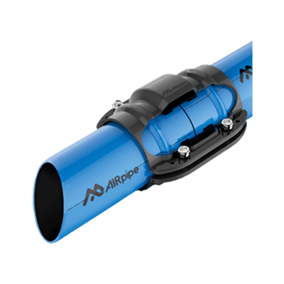
Corrosion Resistance
Aluminum does not develop the same internal rust scale associated with traditional black-iron compressed-air piping.

Modular Industrial Air Distribution
Build or expand a compressed-air or compatible vacuum distribution system with corrosion-resistant aluminum pipe, hoses, connectors, quick drops, flange connections, wall brackets, valves and installation accessories. Browse AIRpipe components by system function, pipe size, connection type and installation requirement.
Quick Answer
An aluminum compressed-air piping system distributes compressed air from the compressor room to equipment, workstations and point-of-use connections throughout a facility. A complete system may include main piping, flexible hoses, connectors, elbows, tees, reducers, quick drops, flange transitions, isolation valves, wall brackets, supports and drains. Modular aluminum systems are commonly selected for corrosion resistance, clean internal surfaces and easier expansion.
System Material Benefits
Aluminum piping combines a clean internal surface with a lightweight, modular component system for industrial, commercial and shop air distribution.
Aluminum does not develop the same internal rust scale associated with traditional black-iron compressed-air piping.
A clean, smooth internal surface helps reduce avoidable friction and pressure loss when the piping is correctly sized.
Reusable connectors, drops, transitions and valves support organized installation without field threading every connection.
Branches, drops and equipment connections can be added when facility layout or compressed-air demand changes.
Aluminum pipe is lighter than many traditional metal piping materials, simplifying handling and support planning.
Dedicated connectors, wall stations, valves and supports help create a maintainable distribution network.
Shop by Component Type
Use the dedicated child categories to find products by component function rather than browsing the entire piping system at once.
Shop rigid aluminum pipe and flexible hose products for main distribution runs, branches, equipment connections and vibration isolation.
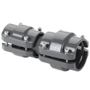
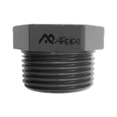
Find unions, elbows, tees, crosses, reducers, adapters and transitions used to join and route AIRpipe sections.
Shop supports, installation hardware, tools, adapters, fasteners and other products used to assemble and secure the system.
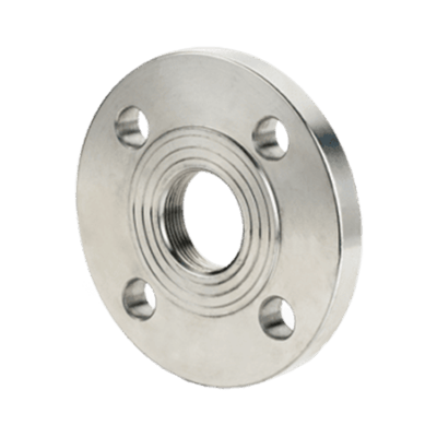
Use flange connections for larger distribution lines, industrial equipment transitions and compatible flanged system interfaces.
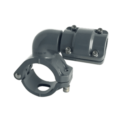
Create workstation drops and branch connections from the main distribution line without rebuilding the complete piping run.
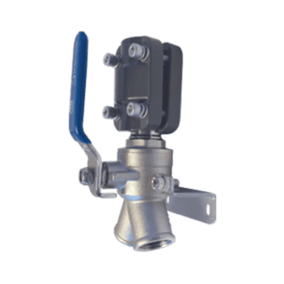
Build organized point-of-use stations with mounted connections, shutoff control and accessible equipment isolation.
Complete Distribution System
Each component performs a defined role in moving air from the compressor room to the final point of use.
| Component | Primary Function | What to Confirm |
|---|---|---|
| Main piping | Carries compressed air through the primary distribution network | Pipe diameter, total CFM, pressure, length and future demand |
| Connectors and fittings | Join pipe sections and create direction changes, branches or transitions | Pipe size, fitting design, branch size and pressure rating |
| Quick drops | Create point-of-use branches from a main or secondary distribution line | Main-line diameter, drop size, airflow and workstation requirement |
| Flange connectors | Transition larger lines to industrial equipment or flanged connections | Pipe diameter, flange standard, bolt pattern and pressure rating |
| Wall brackets and valves | Provide mounted point-of-use air access and isolation | Connection size, valve type, mounting location and service access |
| Supports and accessories | Secure piping and support installation, maintenance or expansion | Pipe size, spacing, structure, hardware and installation method |
| Flexible hose | Isolates vibration or connects moving and stationary equipment | Hose size, length, pressure rating, temperature and connection type |
System Planning
Begin with total airflow demand, system pressure, facility layout and future expansion before selecting pipe diameter or fittings.
The compressor discharge connection does not always represent the correct distribution-line diameter. Main piping may need to be larger to carry total airflow over long distances while maintaining acceptable pressure at the point of use.
Review the Compressed Air Piping Buying Guide and the AIRpipe FAQ and Resource Center for additional planning guidance.
Pressure-drop reminder
Undersized pipe, excessive fittings, long runs and restricted drops can reduce point-of-use pressure. Increasing compressor discharge pressure to compensate may increase energy use without correcting the underlying piping restriction.
Distribution Layout
A loop system allows air to approach a demand point from more than one direction and can help distribute airflow across larger facilities. A branch layout uses a main trunk with individual lines feeding tools and equipment.
The best layout depends on facility size, airflow demand, equipment location, future expansion and acceptable pressure loss.
Use a Loop When You Need
Common Applications
Modular aluminum piping supports compressed-air and compatible vacuum distribution in a wide range of industrial, automotive and commercial environments.
Installation and Expansion
Correct support, alignment, connection preparation and system testing help maintain dependable airflow and reduce leaks.
Use compatible brackets, clips and supports at the spacing required for the pipe size, layout and installation environment.
Verify whether the selected AIRpipe size uses a grab-ring connection, lugged pipe end or another connection method.
Follow manufacturer guidance for expansion, contraction, flexible connections and long straight piping runs.
Route the system to support moisture collection and install appropriate drains, separators and air-treatment equipment.
Inspect and test every connector, valve, branch and equipment transition before placing the complete system into normal service.
Record pipe sizes, valves, drops and connection points to simplify future maintenance and system expansion.
Related Resources
Use these resources for detailed piping selection, sizing, installation and complete system planning.
Frequently Asked Questions
Direct answers about pipe materials, sizing, layouts, pressure drop, vacuum use, components and installation.
An aluminum compressed-air piping system uses corrosion-resistant aluminum pipe and modular fittings to distribute compressed air from the compressor room to equipment, tools and workstations.
Aluminum is lightweight, corrosion resistant and has a smooth internal surface. Modular connectors can also make the system easier to install, maintain and expand than some traditional piping materials.
Choose pipe size using total and peak CFM, operating pressure, line length, number of drops, fitting count and acceptable pressure loss. Main distribution lines may need to be larger than individual equipment connections.
Pressure drop increases when piping is undersized, airflow is high, runs are long or the system contains excessive restrictions. Correct pipe sizing and efficient routing help maintain point-of-use pressure.
A loop allows compressed air to approach demand points from more than one direction. A branch layout uses a main trunk with separate lines feeding tools and equipment. The correct layout depends on facility size and demand.
Some aluminum piping systems are approved for compatible vacuum applications. Confirm the pipe, fittings, seals and pressure or vacuum rating for the specific system before installation.
A system may require aluminum pipe, hoses, connectors, elbows, tees, reducers, quick drops, flange transitions, wall brackets, valves, supports, drains and equipment adapters.
Quick-drop connectors create branch or point-of-use connections from a main distribution line. They are commonly used to add workstation drops without rebuilding the entire piping system.
Yes. Modular aluminum systems can often be expanded with additional branches, drops and connectors. Confirm existing pipe size, airflow capacity, pressure and fitting compatibility before expansion.
Follow the manufacturer’s support spacing, connection-preparation, alignment and pressure-testing requirements. Use compatible brackets and allow adequate clearance for valves, drains and future service.
Have your total CFM, operating pressure, main-line length, facility layout, number of drops, future expansion needs and preferred pipe size ready. A piping specialist can help identify the appropriate AIRpipe products and component categories.