

Air compressors are essential pieces of equipment in numerous manufacturing environments and various industries. They power a wide range of tools, machinery, and processes by converting air into pressurized energy and power. Although air compressors vary in type and capacity, all industrial models include several key components that work cohesively to generate and store compressed air. See how these key parts help businesses and better understand their importance, function, and impact on overall system performance in our air compressor parts diagram below.
Key Components of an Air Compressor
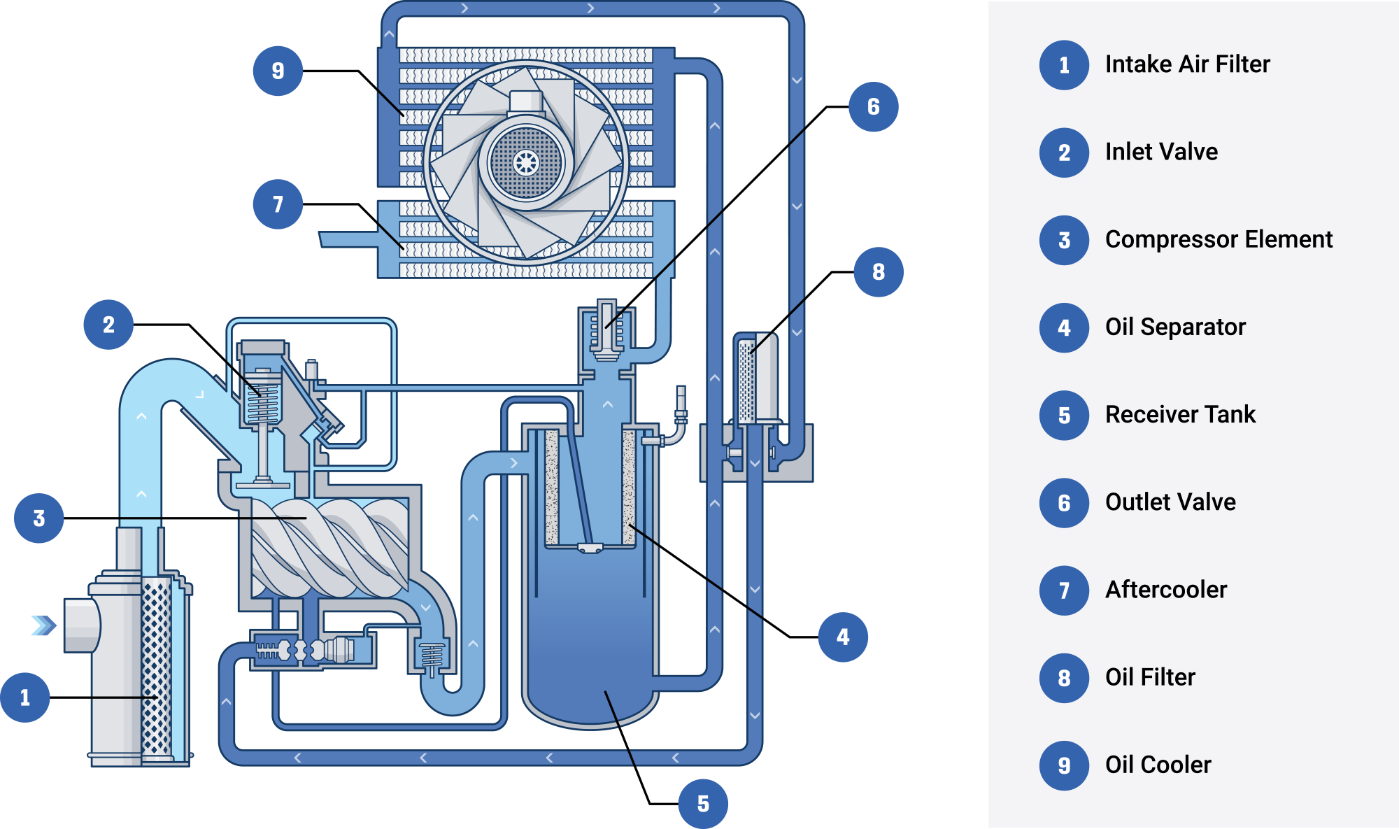
1. Intake Air Filter
The intake air filter is your air compressor’s first line of defense against dirt, dust, and airborne contaminants. As air is drawn in from the environment, the filter catches particles that could otherwise damage the internal components and reduces friction. By preventing particulate buildup, the air filter helps maintain efficiency, reduce wear, and extend the overall service life of the compressor.
How it works: Air enters through the filter housing, the filter traps contaminants, and the cleaner air then proceeds to the inlet valve.
2. Inlet Valve
Sometimes known as the “unloader” or “suction” valve, the inlet valve controls when air can enter the compressor element. This valve’s ability to open or close is crucial for maintaining optimal pressure and flow rates, preventing over-pressurization and excessive energy consumption.
How it works: The inlet valve remains partially or fully open to let ambient air in under normal operation. When the system detects that the maximum operating pressure has been reached, the inlet valve closes to prevent further pressurization. This load/unload cycle ensures the compressor only supplies as much air as needed.
3. Compressor Element
The compressor element is where the actual compression takes place. Two interlacing helical rotors, or screws, spin against each other, drawing in air and progressively reducing its volume to increase pressure. This element is directly responsible for compressing air to the desired pressure level. Efficiency and reliability of the entire system often relies on the design of the compressor element.
How it works (Rotary Screw Example): Air enters at one end of the rotary screws. As the screws rotate, they trap air between the rotors and the compressor housing. The space containing the air reduces in volume as it moves along the rotors, raising air pressure. In an oil-flooded design, oil is injected to lubricate the screws, seal gaps, and help cool the compressed air.
4. Oil Separator
In an oil-flooded rotary screw compressor, oil is mixed with the incoming air to help with cooling and sealing. That means, after compression, the air must be separated from the oil before it goes downstream. This is where the oil separator comes in. The oil separator ensures minimal oil travels to downstream equipment and reduces the risk of contamination in air tools or processes.
How it works: The air-oil mixture exits the compressor element. Centrifugal force and the filters remove the majority of oil droplets. Oil collects and drains back into the system for reuse. Clean, oil-free air then continues to the next stages.
5. Receiver Tank
The receiver tank, also referred to as an air receiver or storage tank, stores the compressed air before it’s sent to the next stage. Having a buffer of pressurized air allows for an immediate, steady supply of air for short, high-demand spikes without waiting for the compressor to ramp up. The receiver tank minimizes system pressure fluctuations, reduces frequent load/unload cycling of the compressor, and can lead to energy savings.
How it works: Air from the compressor is directed into a pressurized tank. Pressure is regulated by sensors and valves to ensure safe operation. The tank acts as an accumulator to smooth out pulsations or rapid changes in air demand.
6. Outlet Valve
The outlet valve is the final control point for air leaving the compressor system. Once the air has been compressed, cooled, and separated from oil, it is ready for use. The air often passes through the outlet valve before going to the facility’s piping. This outlet valve provides a safety shut-off point and helps isolate the system for repairs or maintenance without depressurizing the entire line.
How it works: It typically remains open during normal operation, allowing air to flow to downstream tools or processes. It can be closed during maintenance or when the system needs to be isolated.
7. Aftercooler
During compression, air can heat up substantially. An aftercooler is designed to cool the compressed air back to ambient temperatures. This step also helps remove water vapor, making filtration and drying more effective. By reducing the temperature of air, it makes it safer to handle and improve the performance of downstream equipment. It also prevents excessive moisture from circulating, which can lead to corrosion or damage in tools and piping.
How it works: Hot, high-pressure air flows through the tubes or plates of the aftercooler. Heat is drawn away by the use of ambient air or a cooling fluid, like water, lowering the temperature of the compressed air. The cooled moisture is then typically collected by moisture traps or drains, leaving cool, dry air available for use.
8. Oil Filter
The oil filter removes contaminants from the circulating lubricating oil. Because that oil is repeatedly injected into the compressor element, keeping it clean is critical to prevent abrasive damage to the screw rotors and bearings. The oil filter protects internal components from harsh wear and tear and helps maintain overall system efficiency. This process also extends the life of the oil, reducing the frequency of maintenance and overall costs.
How it works: Oil passes through a filter, collecting dirt, metal fragments, and other particles. Clean oil is circulated back into the compressor and other components.
9. Oil Cooler
Much like the aftercooler is for compressed air, the oil cooler is designed to remove heat from the lubricant before it returns to the compressor element. This process prevents overheating, which can reduce the quality of the oil and damage components. By maintaining stable operational temperatures for both the compressor element and the oil itself, it contributes to the system’s overall reliability and efficiency.
How it works: Hot oil leaving the compressor flows through the oil cooler, utilizing ambient air or a secondary cooling fluid (e.g., water in a water-cooled system) to remove the heat. The cooled oil is returned and is ready for another cycle.
How AirCompressors.com Can Help
By understanding how each of these key components function, manufacturers and other industry personnel can make informed decisions about air compressor selection, maintenance, and process optimization.
At AirCompressors.com, we carry an array of piston compressors and oil injected rotary screw compressors, along with air compressor parts, lubricants, dryers & filters, and more. Our goal is to ensure you have on demand access to the best compressors and parts to keep your operations running smoothly.
Need assistance determining which compressor is right for you? View our resources or contact our team and our experts will guide you to what works best for your business.